Eureka AIR delivers breakthrough ideas for toughest innovation challenges, trusted by R&D personnel around the world.

Condensation device and automobile exhaust emission system

A technology of air flow and channels, which is applied in the field of condensation devices and automobile exhaust emission systems, can solve the problems of complex devices, power consumption, and high cost, and achieve the effects of reducing particle number, increasing eddy current intensity, and simple structure

Active Publication Date: 2021-03-30
ANHUI JIANGHUAI AUTOMOBILE GRP CORP LTD
View PDF6 Cites 0 Cited by
  • Summary
  • Abstract
  • Description
  • Claims
  • Application Information

AI Technical Summary

Problems solved by technology

The most common way of coagulation is charge coagulation, but the device for creating an electric field is relatively complicated, consumes electricity, and costs a lot

Method used


Image

  • Condensation device and automobile exhaust emission system
  • Condensation device and automobile exhaust emission system
  • Condensation device and automobile exhaust emission system

Examples


Embodiment Construction

[0029] The following will clearly and completely describe the technical solutions in the embodiments of the present invention with reference to the accompanying drawings in the embodiments of the present invention. Obviously, the described embodiments are only part of the embodiments of the present invention, not all of them. Based on the embodiments of the present invention, all other embodiments obtained by persons of ordinary skill in the art without creative efforts fall within the protection scope of the present invention.

[0030] It should be noted that if there is a directional indication (such as up, down, left, right, front, back, outside, inside...) in the embodiment of the present invention, the directional indication is only used to explain the direction in a certain posture ( As shown in the accompanying drawings), if the specific posture changes, the directional indication will also change accordingly.

[0031] In addition, if there are descriptions involving "f...


PUM


Abstract

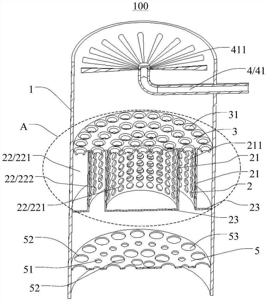
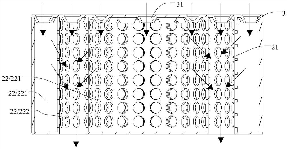
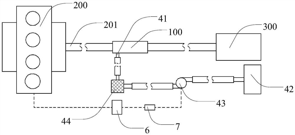
The invention discloses a coagulation device and a vehicle exhaust emission system, and relates to the technical field of vehicle exhaust treatment. The coagulation device comprises a shell and at least one coagulation unit. The shell is provided with a wind inlet and a wind outlet, and ducts communicating with the wind inlet and the wind outlet are formed. All the coagulation units are arranged in the ducts. Each coagulation unit comprises a plurality of sleeves which are sleeved and are in clearance fit with one another, and wind screens, wherein each sleeve extends in the gas flowing direction and is provided with openings in the two ends, a plurality of through holes run through the cylinder wall of each sleeve, channels are formed between the sleeve on the outermost layer and the shell, between every two adjacent sleeves and in the sleeve on the innermost layer correspondingly, wind inlet sides of at least part of channels correspond to the wind inlet, all the channels include thefirst channels and the second channels which are staggered, wind outlet sides of the second channels correspond to the wind outlet, and the wind screens are arranged on the wind outlet sides of the first channels and used for allowing the gas flow in the first channels to enter the second channels through the through holes.

Description

technical field [0001] The invention relates to the technical field of automobile tail gas treatment, in particular to a condensation device and a car tail gas discharge system. Background technique [0002] Automobile emissions are becoming more and more stringent, and the national 6 stage emission will include the number of particles in the emission control. The control of particle number emission has become a difficult problem for automobile emissions, especially for gasoline engines. The control of particles emitted by automobiles in off-machine purification mainly relies on particle traps. However, particle traps have a certain efficiency in capturing particles, especially the particle traps of gasoline engines, which are less efficient, mainly because too small particles cannot be trapped. [0003] The so-called coagulation is the process in which small particles merge into large particles through some mechanisms. The factors that promote particle coagulation include...

Claims


Application Information

Patent Timeline
Patent Type & Authority Patents(China)
IPC IPC(8): F01N3/02F01N3/037F01N3/021B01D45/16
CPCB01D45/16F01N3/02F01N3/021F01N3/037
Inventor 陆荣荣赵文仲丁光辉潘月成滕建耐
Owner ANHUI JIANGHUAI AUTOMOBILE GRP CORP LTD
Why Eureka
Eureka Blog
Learn More