
A drainage and noise reduction device and method for improving cooling fan backflow

A heat dissipation fan and noise reduction technology, applied to components of pumping devices for elastic fluids, pump devices, power electronics modification, etc., to achieve the effects of reducing broadband and discrete single-tone noise, suppressing eddy currents, and increasing heat transfer

Active Publication Date: 2021-10-08
SHANGHAI JIAO TONG UNIV +1
View PDF8 Cites 0 Cited by
  • Summary
  • Abstract
  • Description
  • Claims
  • Application Information

AI Technical Summary

Problems solved by technology

[0005] In view of the above-mentioned defects of the prior art, and in view of the above-mentioned defects of the existing products, the technical problem to be solved by the present invention is how to control and improve the backflow and suppress the generation of eddy currents in a small space without affecting the fan inflow and outflow. Achieves the effect of reducing broadband and discrete single-tone noise

Method used


Image

  • A drainage and noise reduction device and method for improving cooling fan backflow
  • A drainage and noise reduction device and method for improving cooling fan backflow
  • A drainage and noise reduction device and method for improving cooling fan backflow

Examples


Embodiment 1

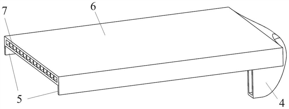
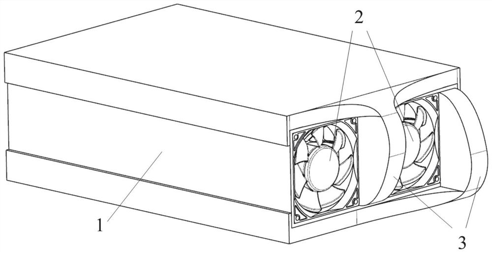
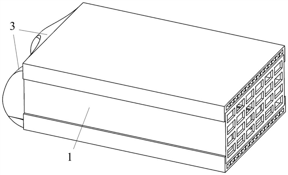
[0031] Such as figure 1 , 2 , 3, 4, 5, and 6, the drainage and noise reduction device 3 for improving the backflow of the cooling fan in this embodiment includes a drainage passage 4 and a fixed bracket 5, and the drainage passage 4 is a curved pipeline, which is adapted to the shape of the narrow space 1 , the drainage channel 4 is arranged on the fixed bracket 5, and the fixed bracket 5 is arranged on the outside of the narrow space 1, the inlet of the drainage channel 4 is arranged in the inflow area of ​​the cooling fan 2 to form a closed flow channel, and the drainage channel 4 is bent so that the outlet extends to the narrow space 1 outside the outer frame, and the drainage channel 4 itself constitutes the interlayer 6 of the narrow space 1, and the interlayer is provided with ribs 7 to enhance heat exchange.

[0032] Such as Figure 7 As shown, in a narrow space, when there are a large number of components downstream of the cooling fan, the exhaust of the fan is hinde...

Embodiment 2

[0037]On the basis of Embodiment 1, the combined form of the drainage passage can be considered, and a hole is opened on the outer frame of the narrow space in the outflow area of ​​the cooling fan 2 to communicate with the interlayer 6 to form a new drainage passage. When the narrow space installation permits, the two interlayers 6 can be connected to form an annular interlayer to wrap the outer frame of the narrow space. At this time, it is a combined form in which multiple drainage channel inlets correspond to one outlet.

Embodiment 3

[0039] The application of this embodiment to the case where a plurality of cooling fans 2 are connected in series does not change the principle and function mode of the air drainage device, and the present invention can also be applied to complex fan arrangements.


PUM


Abstract

The invention discloses a drainage and noise reduction device for improving the backflow of a cooling fan, which includes a drainage passage and a fixing bracket, wherein the drainage passage is arranged on the fixing bracket, and is arranged inside a narrow space or through the fixing bracket. On the outside, the inlet of the drainage channel is arranged in the inflow area or the outflow area of ​​the cooling fan, and forms a closed flow channel with the inflow area or the outflow area, and the outlet of the drainage channel extends beyond the outer frame of the narrow space . The invention also discloses a method for making and using the drainage noise reduction device. The invention can reduce the influence of the backflow caused by the downstream components of the cooling fan on the inflow and outflow of the cooling fan in a narrow space, so that the flow of the cooling fan is smooth, and the broadband and discrete unit of the cooling fan can be reduced without reducing or even improving the cooling performance of the cooling fan. sound noise.

Description

technical field [0001] The invention relates to the technical field of fan heat dissipation and noise reduction, in particular to a drainage and noise reduction device and a method thereof for improving backflow of a cooling fan in a narrow space. Background technique [0002] Cooling fans are often used for heat dissipation in narrow spaces such as server cabinets and power modules. Due to the tight arrangement of electronic devices in a small space and severe heat generation, it usually requires multiple cooling fans to form a cooling unit to force cooling. There are generally two ways to install the cooling fan: inward air outlet and outward air outlet. In order to meet the air volume requirements, cooling fans often work at a higher speed, which brings high aerodynamic noise. In addition, when the cooling fan blows air inward, due to the limitation of the narrow space itself and the obstruction of internal downstream components, the airflow may turn back and form backf...

Claims


Application Information

Patent Timeline
Patent Type & Authority Patents(China)
IPC IPC(8): F04D29/66F04D29/64F04D25/16H05K7/20
CPCF04D25/166F04D29/646F04D29/663F04D29/667H05K7/20718H05K7/20909
Inventor 孙宗翰田杰欧阳华
Owner SHANGHAI JIAO TONG UNIV
Learn More