Eureka AIR delivers breakthrough ideas for toughest innovation challenges, trusted by R&D personnel around the world.

Glasses frame cleaning and spin-drying device based on centrifugal principle

A spectacle frame and equipment technology, applied in the field of spectacle frames, can solve the problems of secondary pollution, secondary pollution of spectacle frames, failure to improve the cleaning efficiency of spectacle frames, etc., and achieve the effect of synchronous cleaning and drying

Inactive Publication Date: 2020-08-04
南通积瑞丝纺织品有限公司
View PDF8 Cites 0 Cited by
  • Summary
  • Abstract
  • Description
  • Claims
  • Application Information

AI Technical Summary

Problems solved by technology

However, after cleaning and drying, the above-mentioned cleaning machine still needs workers to manually install the glasses frames on the hanging clips. Although the daily cleaning efficiency can be greatly improved, in the later drying process, workers still need to take out the glasses after cleaning. The frame will be dried for the next round. In this process, the cleaned spectacle frame will inevitably produce secondary pollution and fine particles, which still cannot improve the cleaning efficiency of the spectacle frame.
[0004] Therefore, we propose a cleaning and drying equipment for spectacle frames based on the centrifugal principle, which realizes the cleaning and drying of spectacle frames through the centrifugal principle, avoiding that the traditional spectacle frame cleaning equipment only has cleaning functions, and subsequent separate cleaning is required. Drying, easy to produce secondary pollution during the drying period

Method used


Image

  • Glasses frame cleaning and spin-drying device based on centrifugal principle
  • Glasses frame cleaning and spin-drying device based on centrifugal principle
  • Glasses frame cleaning and spin-drying device based on centrifugal principle

Examples


Embodiment Construction

[0029] The following will clearly and completely describe the technical solutions in the embodiments of the present invention with reference to the accompanying drawings in the embodiments of the present invention. Obviously, the described embodiments are only some, not all, embodiments of the present invention. Based on the embodiments of the present invention, all other embodiments obtained by persons of ordinary skill in the art without making creative efforts belong to the protection scope of the present invention.

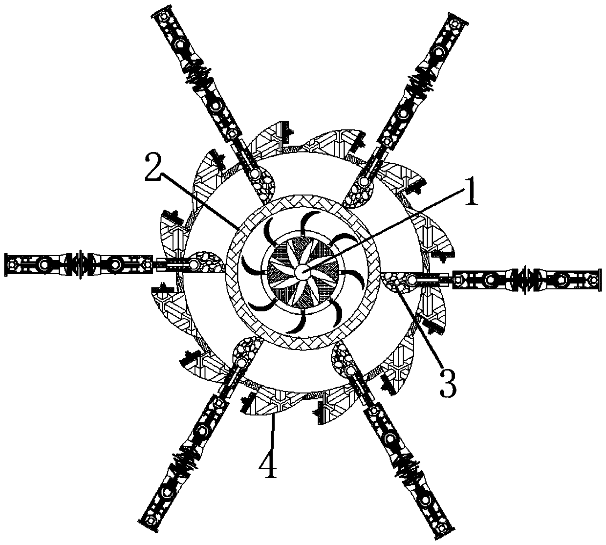
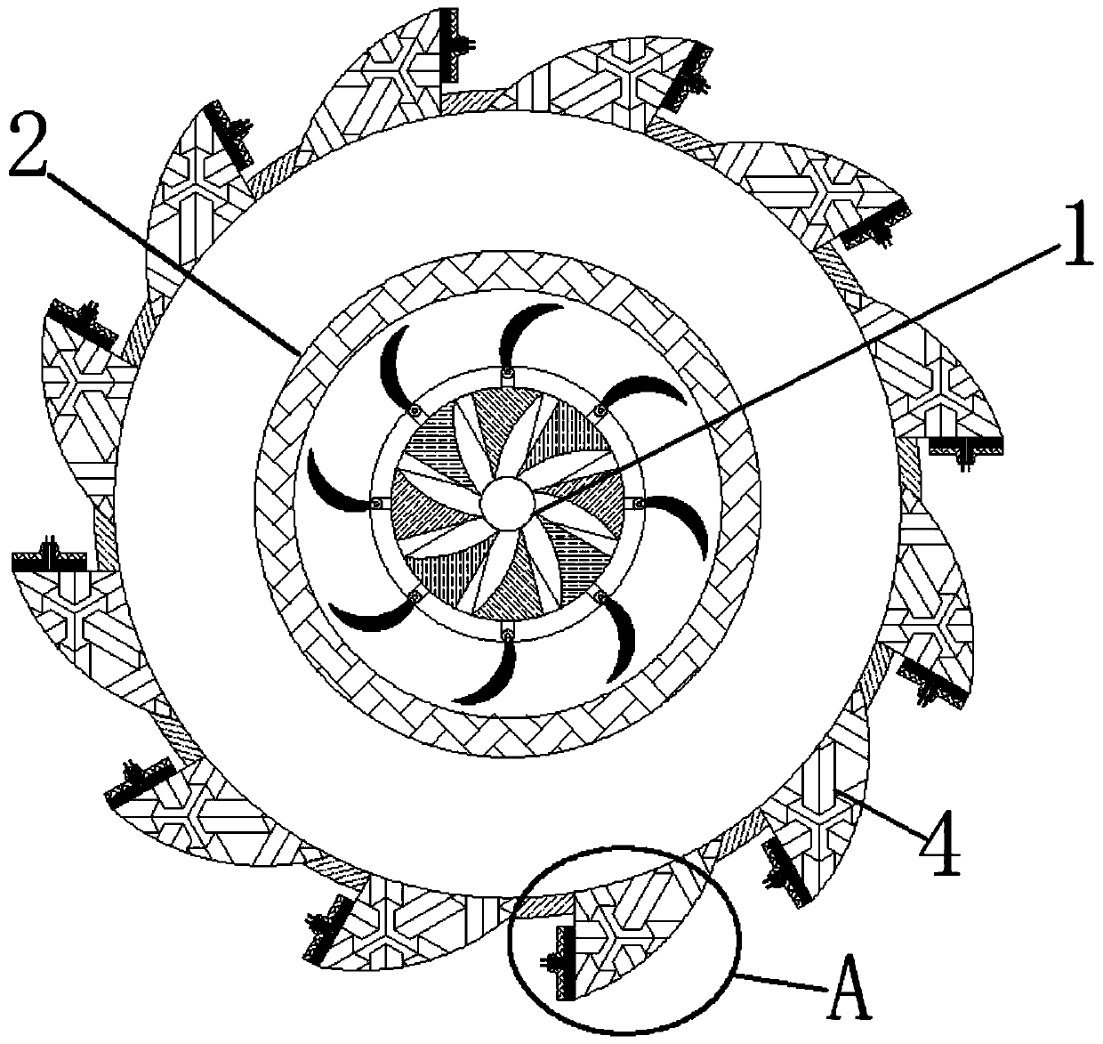
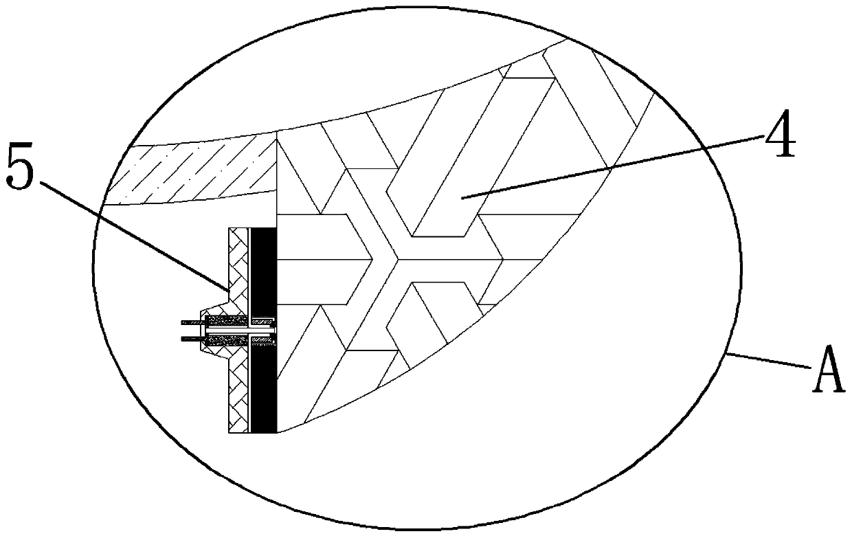
[0030] see Figure 1-10 , a cleaning and drying equipment for spectacle frames based on the centrifugal principle, comprising a driving shaft 1, a driving ring 2 is movably connected to the outside of the driving shaft 1, and a connecting block 3 is movably connected to the outside of the driving ring 2, and the connecting block The outer side of 3 is movably connected with a water tank 4, and the inside of the water tank 4 is movably equipped with a water out...


PUM


Abstract

The invention relates to the technical field of spectacle frames, and further discloses a glasses frame cleaning and spin-drying device based on the centrifugal principle. The device comprises a driving axis, a driving circular ring is movably connected to the outer side of the driving shaft center, and a connecting block is movably lapped to the outer side of the driving circular ring. An inner mounting ring is movably connected to the inner side of an outer mounting ring, an abutting spring is movably connected to the outer side of the inner mounting ring, and a pushing spring is movably connected to the end, away from the inner mounting ring, of the abutting spring. By starting a driving device, the driving axis rotates along with the driving device, further the driving circular ring rotates, the connecting block rotates along with the driving circular ring, and further a spectacle frame main body clamped by the clamping blocks is driven to synchronously keep rotating, the water stored in a water tank is sprayed from the water outlet to clean the spectacle frame main body clamped by the clamping blocks, and after cleaning, the water outlet stops discharging water to spin-dry thecleaned water spots on the spectacle frame main body clamped by the clamping blocks, so that the synchronous cleaning and spin-drying are realized.

Description

technical field [0001] The invention relates to the technical field of spectacle frames, in particular to a cleaning and drying device for spectacle frames based on the centrifugal principle. Background technique [0002] Glasses are lens lenses embedded in the frame and worn in front of the eyes to improve vision, protect eyes or for decoration. Mirrors can correct a variety of vision problems, including nearsightedness, farsightedness, astigmatism, presbyopia or strabismus, amblyopia, etc. During the production process of spectacle frames, due to other impurities and pollutants sticking to the surface, after production and molding, the spectacle frames need to be cleaned, dried, and then painted. [0003] In order to improve production efficiency, the Chinese utility model patent with the application date of February 04, 2016 and the application number 201620119029.6 discloses a roller-type spectacle frame cleaning machine, including a frame, a main shaft, a cleaning cyli...

Claims


Application Information

Patent Timeline
Patent Type & Authority Applications(China)
IPC IPC(8): G02C13/00
CPCG02C13/006
Inventor 袁旦妮
Owner 南通积瑞丝纺织品有限公司
Why Eureka
Eureka Blog
Learn More