Aerial fixed type edge cleaning machine

An edge cleaning machine and fixed technology, applied in the direction of ceramic molding machines, auxiliary molding equipment, manufacturing tools, etc., can solve the problems of resource waste and economic loss, high cleaning difficulty, unfavorable packaging, etc., to increase security and simplify action steps , High cleaning efficiency

Pending Publication Date: 2022-03-11
江苏润鼎智能装备科技有限公司
View PDF0 Cites 0 Cited by
  • Summary
  • Abstract
  • Description
  • Claims
  • Application Information

AI Technical Summary

Problems solved by technology

[0002] Air-entrained concrete block is an excellent new building material. In the production process, a large cubic embryo needs to be manufactured first, and then cut into several blocks according to the required size from this large embryo. During the cutting process, the six sides of the green body need to be cut and processed to make it flat. Generally, a few centimeters thick surface layer needs to be cut off; when the green body is demoulded, the side plates will carry the green body and flow into the subsequent production line. The cut material on the four sides in the vertical direction falls in the pit and is washed away. The cutting layer on the upper side can be sucked off by the vacuum suction cup installed above, while the lower long side between the side plate and the blank The layer is more difficult to clean. If it is not cleaned, it will enter the autoclave for maintenance. The volume of this part generally accounts for 2% -3.5% of the volume of the finished product. After the product is out of the autoclave, this part is difficult to use and will cause great damage Large waste of resources and economic losses are also not conducive to later packaging and other processes

Method used


Image

  • Aerial fixed type edge cleaning machine
  • Aerial fixed type edge cleaning machine
  • Aerial fixed type edge cleaning machine

Examples


Embodiment Construction

[0029] The following will clearly and completely describe the technical solutions in the embodiments of the present invention with reference to the drawings in the embodiments of the present invention.

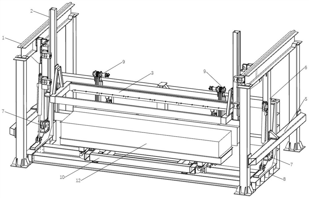
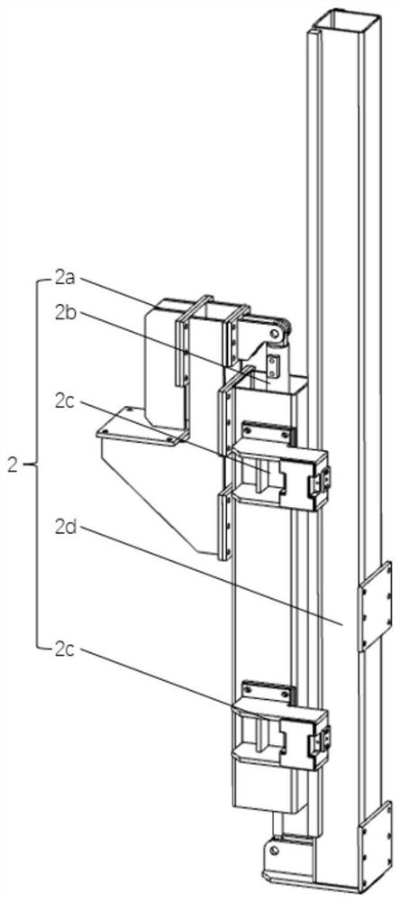
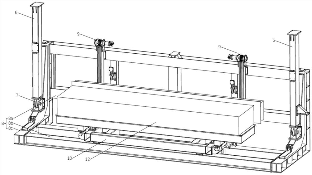
[0030] Such as Figure 1~Figure 6 As shown, the aerial fixed edge cleaning machine includes a pair of parallel and symmetrical gantry frames 1, and each gantry frame 1 is composed of 2 columns and 1 beam at the top. H-shaped steel, the two ends of the beam are concave and the depression is connected with the column. When the gantry structure is erected and disassembled, there are always two columns connected into one body, which is safe and reliable. The distance between two gantry frames is 7.5m-8.5m. , with ample space between them, which is convenient for setting various devices required for edge cleaning, and can adapt to the size of the mainstream aerated concrete body 12 (about 6m in length) on the market; Mechanism 2, the bottom of the lifting mechanism 2 is connected ...


PUM


Abstract

The invention relates to the technical field of aerated concrete block production equipment, in particular to an aerial fixed type edge cleaning machine which comprises a portal frame, a lifting mechanism is arranged on the inner side of the portal frame, an edge cleaning mechanism is connected to the bottom of the lifting mechanism, and the lifting mechanism is connected with a left-right synchronizing mechanism. The edge cleaning mechanism comprises a triangular support and a frame connected to the lower portion of the triangular support, the frame is provided with a scraper blade and a scraper, and the blade end of the scraper blade is located on the outer side of the frame. The portal frame is further provided with a flat beam and is fixedly provided with a square tube, the bottom of the square tube is provided with a hinge device, the hinge device is connected with a roll-over stand, and the roll-over stand is provided with a sensor; the device adopts an aerial fixed design, does not need to move, is suspended for edge cleaning, and is convenient for waste to fall off; the edge cleaning process is smoothly linked; the power mechanism is reasonable, the translation and turnover process of the blank is smooth, the lifting actions on two sides are synchronous, and the fragile blank is not easy to damage; and simultaneous cleaning of the side plate and the aerated concrete blank body is realized.

Description

technical field [0001] The invention relates to the technical field of production equipment for aerated concrete blocks, in particular to an aerial fixed edge cleaner. Background technique [0002] Air-entrained concrete block is an excellent new building material. In the production process, a large cubic embryo needs to be manufactured first, and then cut into several blocks according to the required size from this large embryo. During the cutting process, the six sides of the green body need to be cut and processed to make it flat. Generally, a few centimeters thick surface layer needs to be cut off; when the green body is demoulded, the side plates will carry the green body and flow into the subsequent production line. The cut material on the four sides in the vertical direction falls in the pit and is washed away. The cutting layer on the upper side can be sucked off by the vacuum suction cup installed above, while the lower long side between the side plate and the blank...

Claims


Application Information

Patent Timeline
IPC IPC(8): B28B11/22B28B17/00
CPCB28B11/22B28B17/00
Inventor 张立煌陈勇马犇
Owner 江苏润鼎智能装备科技有限公司
Why Eureka
Try Eureka