
Loudspeaker

A loudspeaker, vertical axis technology, applied in the field of loudspeakers, can solve problems such as increasing the height of the loudspeaker

Active Publication Date: 2020-08-04
PSS BELGIUM
View PDF6 Cites 0 Cited by
  • Summary
  • Abstract
  • Description
  • Claims
  • Application Information

AI Technical Summary

Problems solved by technology

[0005] However, the inventors have observed that in some cases, for example when designing a low-profile loudspeaker (i.e. designing a loudspeaker with a small height measured along its longitudinal axis in the direction of diaphragm movement), when in the forward direction the diaphragm is at Rigid dust cover increases loudspeaker height at maximum range

Method used


Image

  • Loudspeaker
  • Loudspeaker
  • Loudspeaker

Examples


Embodiment Construction

[0058] Aspects and embodiments of the invention will now be discussed with reference to the figures. Other aspects and embodiments will be apparent to those skilled in the art. All documents mentioned herein are hereby incorporated by reference.

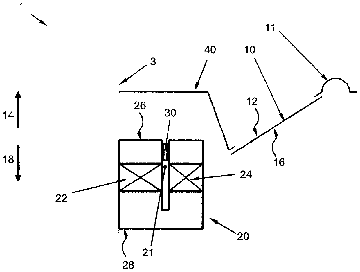
[0059] figure 1 Shown is a loudspeaker 1 designed by the inventors according to known principles. The loudspeaker 1 has a diaphragm 10 with a front surface 12 facing in a forward direction 14 to produce sound radiating outwards from the loudspeaker 1 in a forward direction 14, and a front surface 12 facing in a rearward direction 18. rear surface16. In this example, said forward direction 14 is opposite to said rearward direction 18 and both forward and rearward directions 14 , 18 extend along the longitudinal axis 3 . In this example, the diaphragm 10 is circular, but other shapes are foreseeable.

[0060] The diaphragm 10 is detached from the loudspeaker's frame ( figure 1 not shown in ), the roller suspension 11 is attached ...


PUM


Abstract

A loudspeaker including a diaphragm having a front surface facing in a forward direction for producing sound to be radiated outwardly from the loudspeaker in the forward direction and a back surface facing in a backward direction that is opposite to the forward direction; a magnet unit configured to provide magnetic field in a predetermined region of space; a voice coil rigidly connected to the diaphragm, wherein the voice coil is configured to produce a magnetic field in use which interacts with the magnetic field provided by the magnet unit in the predetermined region of space so as to movethe diaphragm along a longitudinal axis of the loudspeaker; a flexible dustcap attached to the diaphragm and an attachment surface of the loudspeaker that is fixed with respect to the magnet unit andis located radially inwards of the voice coil relative to the longitudinal axis of the loudspeaker.

Description

technical field [0001] The invention relates to a loudspeaker. Background technique [0002] The inventors have observed that in most loudspeakers fitted with a dust cap, the dust cap is usually a rigid element attached to the front surface of the diaphragm, which extends through the aperture of the diaphragm and covers the diaphragm hole. Such holes may be present, for example, in the diaphragm to accommodate magnet units (such as figure 1 shown) or to allow easier attachment of the diaphragm to the voice coil former (such as in WO2017 / 045795A1 figure 1 shown in ). [0003] A typical purpose of a dust cover is to prevent dust, moisture or other foreign matter from entering the magnet unit through the air gap in which the magnetic field is provided by the air gap. A dust cover can also help protect the listener from any unwanted noise (usually high frequency noise) generated behind the speaker diaphragm. [0004] Attached to the front surface of the diaphragm is a dust ...

Claims


Application Information

Patent Timeline
Patent Type & Authority Applications(China)
IPC IPC(8): H04R9/02H04R9/04
CPCH04R9/02H04R9/025H04R9/045H04R1/023
Inventor J·舍本斯
Owner PSS BELGIUM
Learn More