
Method for renovating and repairing soil in iron ore area

An iron ore and soil technology, applied in the restoration of polluted soil, chemical instruments and methods, earth movers/shovels, etc., can solve problems such as the inability to grow plants in the soil, water pollution, ecological environment and human health threats

Inactive Publication Date: 2020-08-07
安徽绪稻康建筑工程咨询有限公司
View PDF5 Cites 5 Cited by
  • Summary
  • Abstract
  • Description
  • Claims
  • Application Information

AI Technical Summary

Problems solved by technology

[0002] Soil is a natural shelter and purification treatment site for various wastes. Soil accepts pollutants. When there are too many pollutants contained in the soil, which affects or exceeds the self-purification ability of the soil, the natural environment in the area will deteriorate. Cause serious damage, such as the soil environment near the iron ore area, due to the impact of iron and steel smelting, the soil near the iron ore area is doped with a large amount of iron ore impurities, after the iron ore veins are used up, resulting in the near iron ore veins The soil cannot grow plants. In addition, the soil in this area can also enter rivers, lakes and groundwater through rainwater washing, which easily causes water pollution and poses a great threat to the ecological environment and human health. For this reason, the present invention has It is necessary to propose a kind of equipment for repairing the soil in the iron ore area, which sequentially separates the soil in the iron ore area from large particles of impurities such as stones, smashes the soil, and separates the iron ore impurities, and then transports the soil back to the ground, which can repair the iron ore. The soil in the mining area is effectively renovated and restored to restore the natural environment of the iron mining area

Method used


Image

  • Method for renovating and repairing soil in iron ore area
  • Method for renovating and repairing soil in iron ore area
  • Method for renovating and repairing soil in iron ore area

Examples


Embodiment Construction

[0081] The specific implementation manners of the present invention will be further described below in conjunction with the drawings and examples. The following examples are only used to illustrate the technical solution of the present invention more clearly, but not to limit the protection scope of the present invention.

[0082] A method for renovating and repairing soil in an iron ore area, the steps of which are:

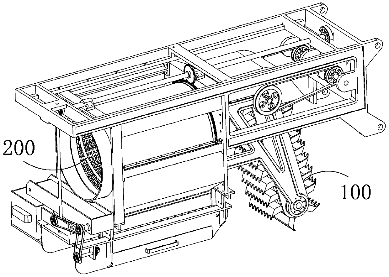
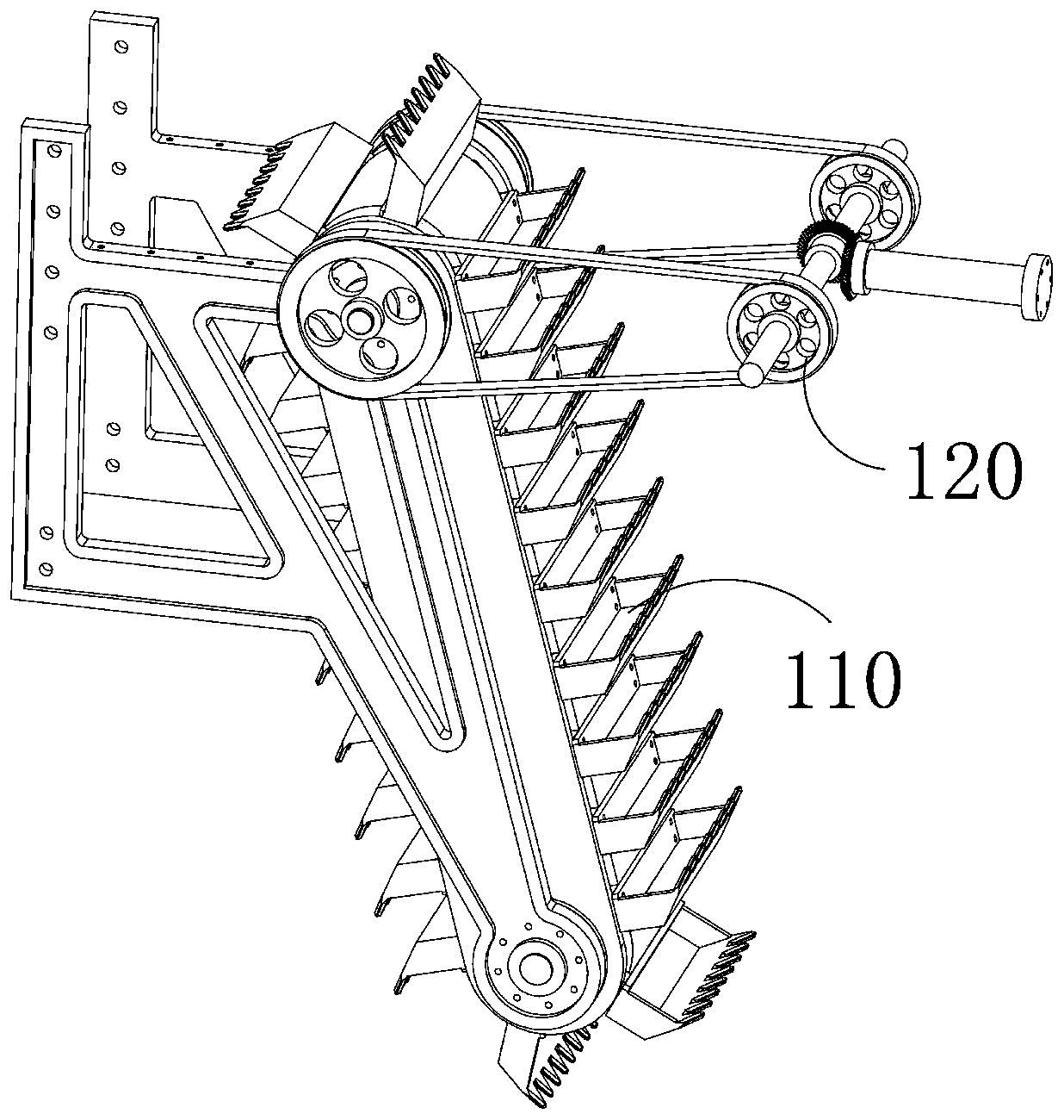
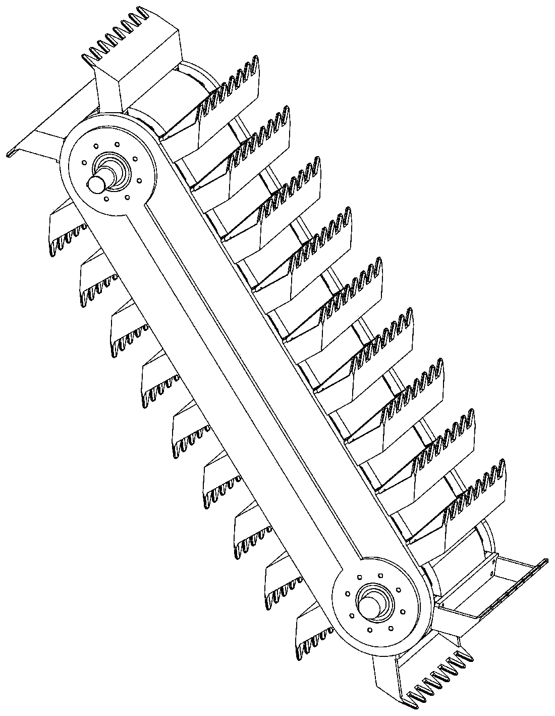
[0083] S1: The soil excavation device 100 installed on the main frame excavates the soil in the iron ore area;

[0084] The main frame body is fixed and suspended on tractors and other traveling equipment. The soil excavation device 100 includes a soil excavation mechanism 110 and a power connection mechanism 120. The power connection mechanism 120 is used to receive the power of the traveling equipment and transmit it to the soil excavation mechanism 110;

[0085] The earth excavation mechanism 110 includes a fixed bracket, a rotating roller 111, an inner sup...


PUM


Abstract

The invention discloses a method for renovating and repairing soil in an iron ore area. The method comprises the steps that a soil excavating device excavates the soil in the iron ore area; excavatedsoil is guided into the separation mesh enclosure by the guide plate, meanwhile, the separation mesh enclosure rotates and enables the soil to be smashed, so impurities such as stones are conveyed tothe direction of the discharging end of the separation mesh enclosure, and the other soil falls down through the discharging notch; impurities such as stones are discharged through the impurity discharging mechanism; soil and iron ore impurities fall down into the soil beating and crushing mechanism through the discharging notch to be beaten and crushed; the crushed soil downwards falls onto the mounting shell; meanwhile, the belt wheel connecting assembly pulls the soil to move through the scraping plate, the soil finally falls off and returns to the ground again, the iron ore impurities areattracted to the outer surface of the mounting shell through the magnetic plate, and when the iron ore impurities move to the position over the iron ore storage shell, the iron ore impurities can fallinto the iron ore storage shell downwards due to the fact that the non-magnetic plate replaces the magnetic plate at the moment.

Description

technical field [0001] The invention relates to the field of ecological environment restoration, in particular to a soil restoration method in an iron mining area. Background technique [0002] Soil is a natural shelter and purification treatment site for various wastes. Soil accepts pollutants. When there are too many pollutants contained in the soil, which affects or exceeds the self-purification ability of the soil, the natural environment in the area will deteriorate. Cause serious damage, such as the soil environment near the iron ore area, due to the impact of iron and steel smelting, the soil near the iron ore area is doped with a large amount of iron ore impurities, after the iron ore veins are used up, resulting in the near iron ore veins The soil cannot grow plants. In addition, the soil in this area can also enter rivers, lakes and groundwater through rainwater washing, which easily causes water pollution and poses a great threat to the ecological environment and ...

Claims


Application Information

Patent Timeline
IPC IPC(8): B09C1/00B07B15/00B02C1/00B02C23/02B03C1/22B07B1/22E02F3/08E02F7/06
CPCB02C1/00B02C23/02B03C1/22B07B1/22B07B15/00B09C1/00E02F3/08E02F3/082E02F3/087E02F7/06
Inventor 梁昌喜
Owner 安徽绪稻康建筑工程咨询有限公司
Learn More