Iron ore area soil renovating and repairing assembly

A technology of iron ore and soil, applied in the field of soil restoration components in iron ore, can solve problems such as high iron ore impurity content, soil unable to grow plants, ecological environment and human health threats

Inactive Publication Date: 2020-08-04
安徽绪稻康建筑工程咨询有限公司
View PDF8 Cites 1 Cited by
  • Summary
  • Abstract
  • Description
  • Claims
  • Application Information

AI Technical Summary

Problems solved by technology

[0002] Soil is the loose surface layer on the surface of the earth's land that is composed of minerals, organic matter, water, air, and organisms. Humans can obtain food by planting crops on the soil, and can also obtain meat and eggs by grazing livestock. And so on food, once the soil is polluted and destroyed, it will have a great impact on the living environment of human beings. Iron is the metal that was first discovered in the world, the most widely used, and the most used. It is widely used in various fields of industry, etc. The soil near the iron ore area, due to the smelting of iron ore, leads to a high content of iron ore impurities in the soil. After the iron ore veins are used up, the soil near the iron ore veins cannot grow plants. In addition, the The soil in the area can also enter rivers, lakes and groundwater by rainwater, which is easy to cause water pollution and poses a great threat to the ecological environment and human health. The equipment, which sequentially separates large particles of impurities such as stones from the soil in the iron ore area, smashes the soil, and separates the iron ore impurities, then transports the soil back to the ground, which can effectively renovate and repair the soil in the iron ore area and restore iron The natural environment of the mining area

Method used


Image

  • Iron ore area soil renovating and repairing assembly
  • Iron ore area soil renovating and repairing assembly
  • Iron ore area soil renovating and repairing assembly

Examples


Embodiment Construction

[0067] The specific implementation manners of the present invention will be further described below in conjunction with the drawings and examples. The following examples are only used to illustrate the technical solution of the present invention more clearly, but not to limit the protection scope of the present invention.

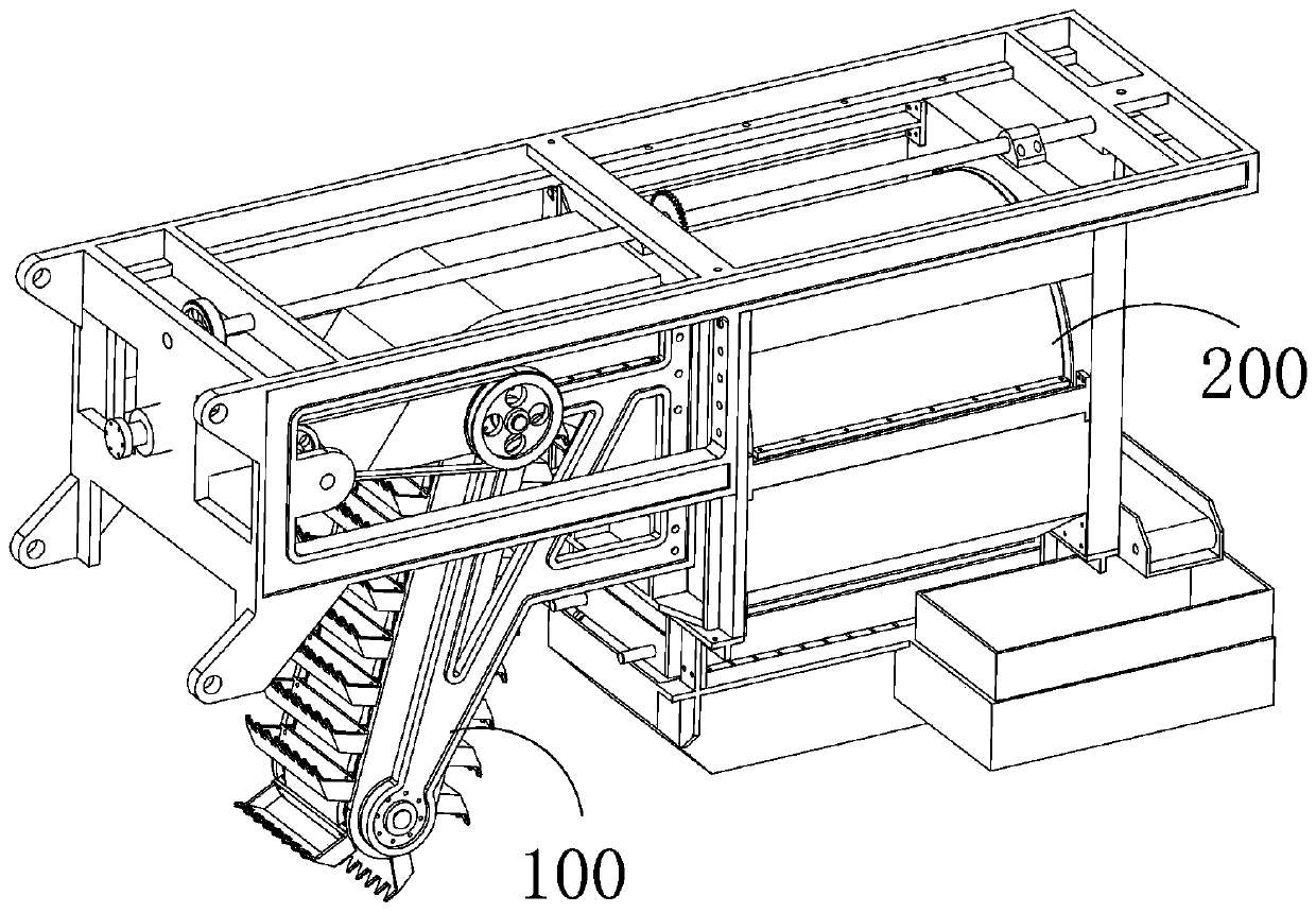
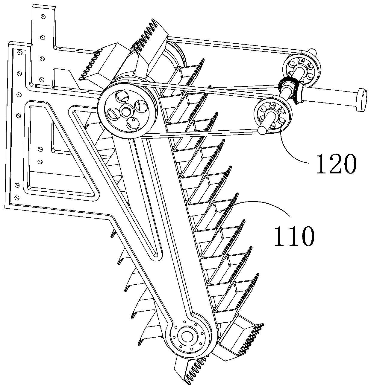
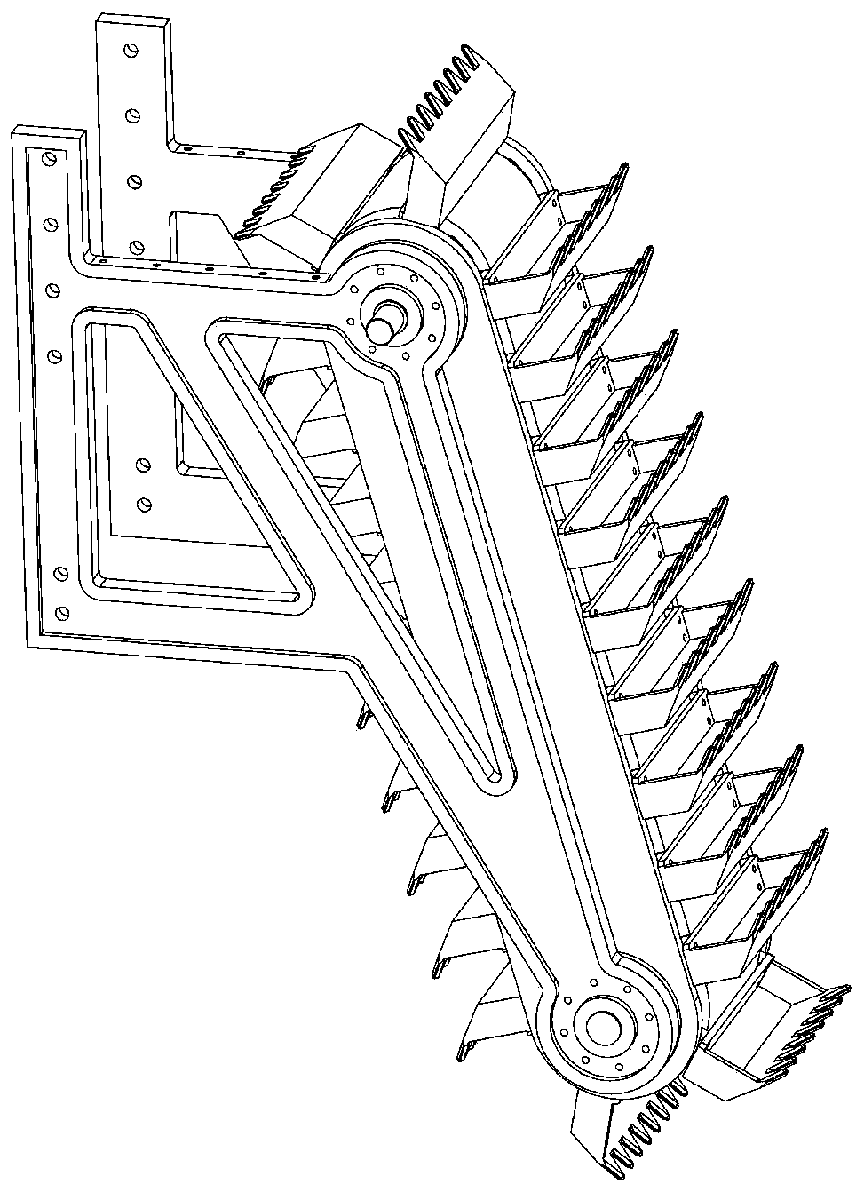
[0068] Soil refurbishment and restoration equipment in small-scale iron mining areas, which includes a main frame body, a soil excavation device 100, and a soil impurity separation device 200. Installed on the main frame body, the soil excavation device 100 is used to excavate the soil in the iron ore area and transport the excavated soil to the soil impurity separation device 200 during the process of following the traveling equipment. The soil is successively processed by filtering large particles of impurities such as stones, smashing the soil, and separating iron ore impurities, and then transporting the soil back to the ground.

[0069] The earth exca...


PUM


Abstract

The invention provides an iron ore area soil renovating and repairing assembly. The iron ore area soil renovating and repairing assembly comprises a main frame body, a connecting shaft (121), an impurity separation mechanism (210), an impurity discharge mechanism (220), a soil beating and crushing mechanism (230) and an iron ore impurity separation mechanism (240), wherein the main frame body is fixedly suspended and mounted on advancing equipment such as a tractor; the connecting shaft (121) is movably mounted on the main frame body and can rotate around the axial direction of the connectingshaft; the connecting shaft (121) is further coaxially and fixedly connected with a power shaft of the advancing equipment. The impurity separation mechanism (210) is used for receiving soil in an iron ore area and filtering large-particle impurities such as stones; the impurity discharge mechanism (220) is used for receiving and storing the large-particle impurities such as stones generated in the separation process of the impurity separation mechanism (210); the soil smashing mechanism (230) is used for receiving the soil filtered by the impurity separation mechanism (210) and smashing the soil, and the iron ore impurity separation mechanism (240) is used for receiving the smashed soil and filtering iron ore impurities of the smashed soil.

Description

technical field [0001] The invention relates to the field of ecological environment restoration, in particular to a soil restoration component in an iron ore area. Background technique [0002] Soil is the loose surface layer on the surface of the earth's land that is composed of minerals, organic matter, water, air, and organisms. Humans can obtain food by planting crops on the soil, and can also obtain meat and eggs by grazing livestock. And so on food, once the soil is polluted and destroyed, it will have a great impact on the living environment of human beings. Iron is the metal that was first discovered in the world, the most widely used, and the most used. It is widely used in various fields of industry, etc. The soil near the iron ore area, due to the smelting of iron ore, leads to a high content of iron ore impurities in the soil. After the iron ore veins are used up, the soil near the iron ore veins cannot grow plants. In addition, the The soil in the area can also...

Claims


Application Information

Patent Timeline
Patent Type & Authority Applications(China)
IPC IPC(8): B09C1/00B02C19/00B02C1/00B02C23/00B02C23/02B03C1/20B03C1/30A01B77/00A01B43/00
CPCA01B43/00A01B77/00B02C1/00B02C19/005B02C23/00B02C23/02B03C1/20B03C1/30B09C1/00
Inventor 梁昌喜
Owner 安徽绪稻康建筑工程咨询有限公司
Why Eureka
Try Eureka