LED wave flush soldering jig

A wave crest and fixture technology, which is applied in the field of LED wave crest flat welding fixtures, can solve problems such as unguaranteed product quality, easy falling off or displacement of the substrate, and affecting work efficiency, so as to improve welding quality, improve work production efficiency, and ensure The effect of product quality

Pending Publication Date: 2020-08-07
东莞市明固照明科技有限公司
View PDF0 Cites 0 Cited by
  • Summary
  • Abstract
  • Description
  • Claims
  • Application Information

AI Technical Summary

Problems solved by technology

The current LED wave soldering fixtures generally have problems such as the lamp holder and the substrate are easy to fall off or shift, which affects the welding quality, and the solder flows back into the lamp holder, causing the LED lamp to be scalded. The product quality cannot be guaranteed, which affects work efficiency.

Method used


Image

  • LED wave flush soldering jig
  • LED wave flush soldering jig
  • LED wave flush soldering jig

Examples


Embodiment Construction

[0021] The technical solutions in the embodiments of the present invention will be clearly and completely described below. Obviously, the described embodiments are only some of the embodiments of the present invention, not all of them. Based on the embodiments of the present invention, all other embodiments obtained by persons of ordinary skill in the art without making creative efforts belong to the protection scope of the present invention.

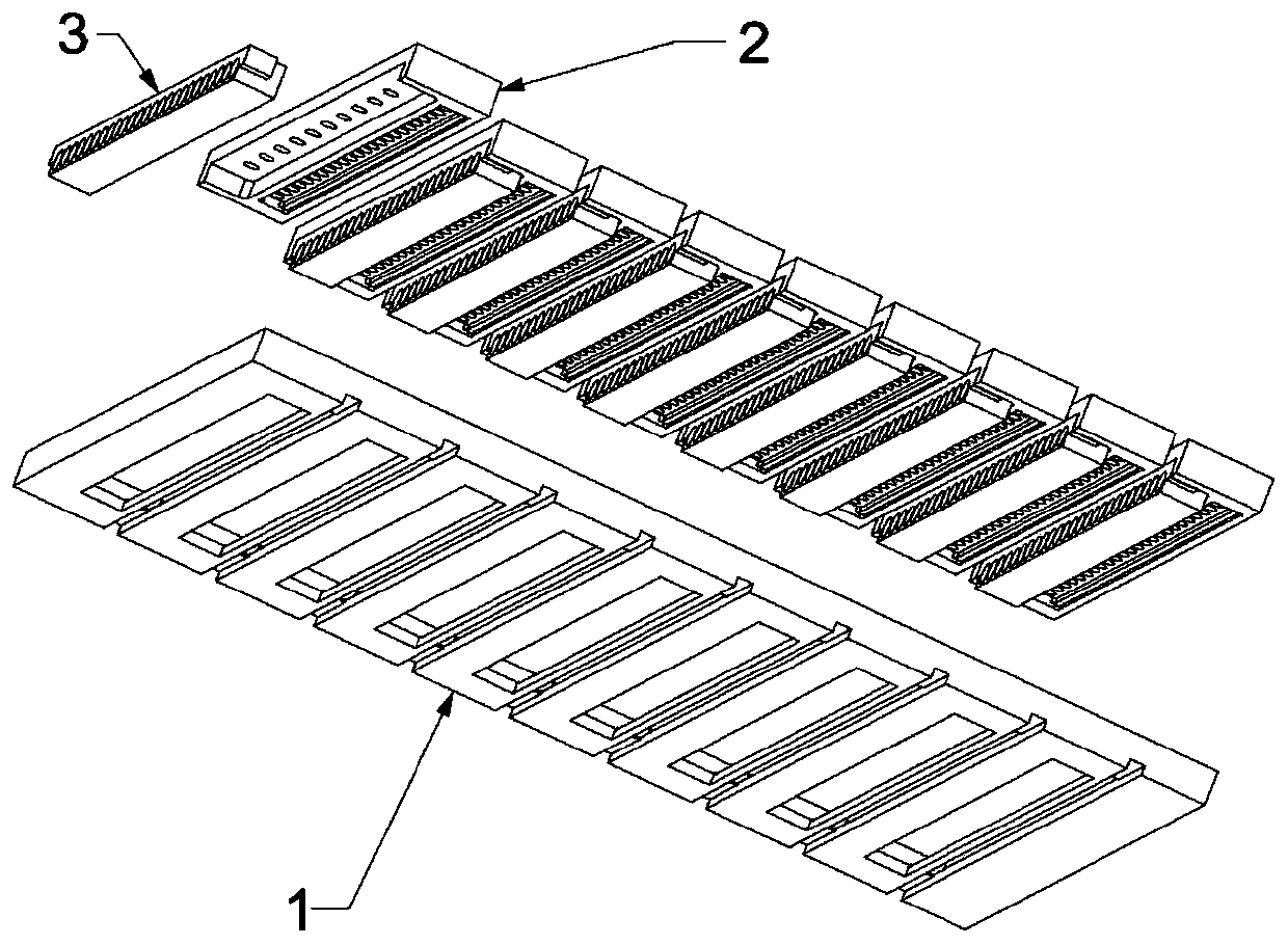
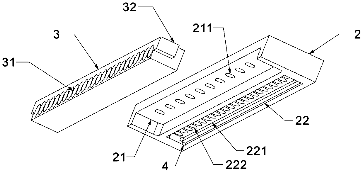
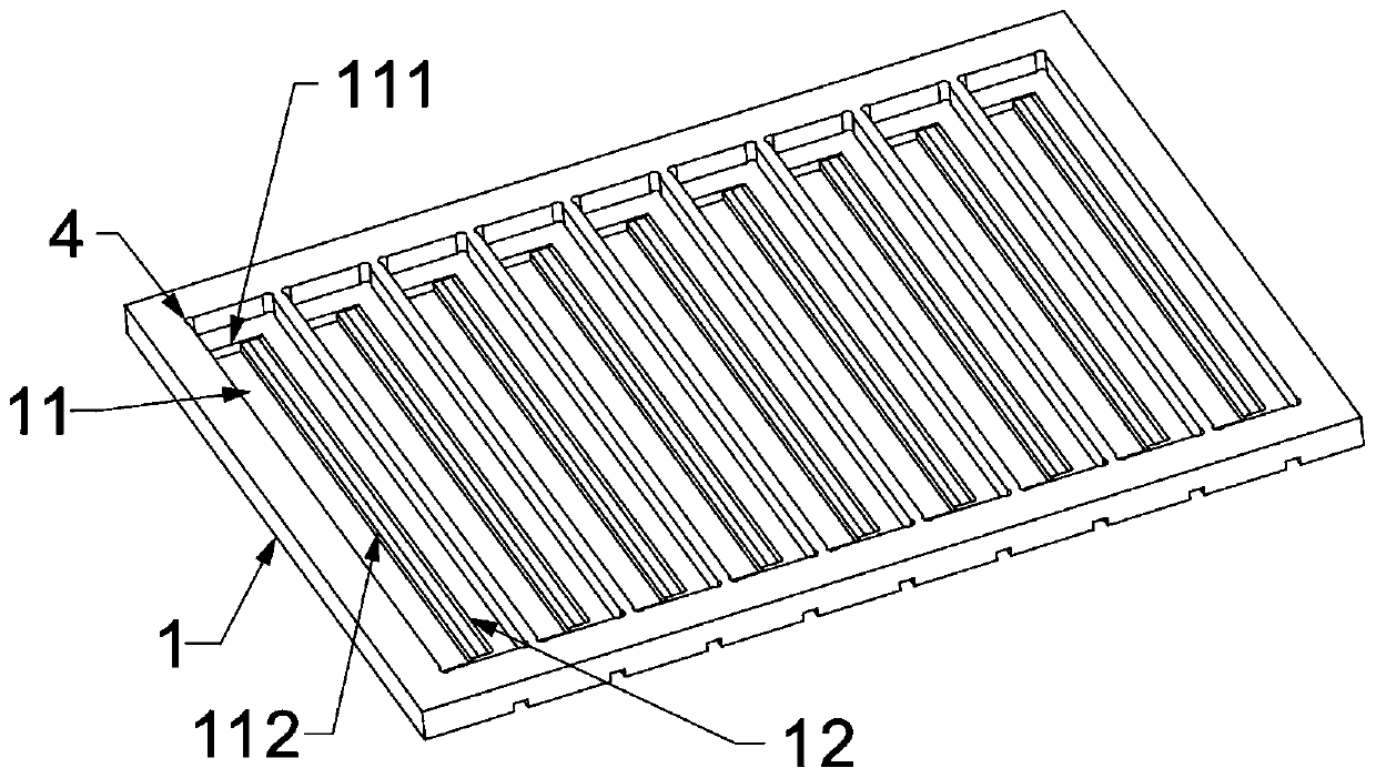
[0022] see figure 1 , LED wave peak flat welding fixture, including supporting plate 1, clamping seat 2, lamp holder 3, supporting plate 1 has a material loading hole 11 matching the shape of the clamping seat 2, and the bottom side of the clamping seat 2 has a lamp holder 3 and a slot 21 that matches the shape of the slot 21 and is provided with a substrate slot 22 for placing the substrate on one side of the slot 21, and a tin flow hole 12 corresponding to the substrate slot 22 is provided on the side of the carrier 1 located at the l...


PUM


Abstract

The invention discloses an LED wave flush soldering jig. The jig comprises a supporting plate, a clamping base and a lamp base, wherein a carrying hole matched with the clamping base in shape is formed in the supporting plate, a clamping groove matched with the lamp base in shape is formed in one side of the bottom of the clamping base, a substrate groove used for containing a substrate is formedin one side of the clamping groove, a tin-flowing hole corresponding to the substrate groove is formed in the supporting plate and located at one side of the carrying hole, a limiting ring which shrinks inwards is formed on the edge of the bottom of the carrying hole, a lamp foot pressing bar is formed, corresponding to the substrate groove, at one side in the limiting ring, and LED lamp holes arearranged in a row in the lamp base to be used for containing LED lamps. According to the jig, (1) by the adoption of a magnet-attracting clamping mode, the phenomena of substrate displacement, fall-off and the like are prevented from occurring in the soldering process, and soldering quality is improved; and (2) by the adoption of the pressing bar design on the supporting plate, the soldering quality is further improved, and the situation that high-temperature soldering tin flows into the LED lamp holes and scalds the LED lamps therein is avoided.

Description

technical field [0001] The invention relates to the technical field of LED production, in particular to an LED wave crest flat welding fixture. Background technique [0002] Wave soldering is to make the welding surface of the plug-in board directly contact with high-temperature liquid tin to achieve the purpose of welding. The high-temperature liquid tin maintains a slope, and a special device makes the liquid tin form a wave-like phenomenon, so it is called "wave soldering". The main material is solder bar. [0003] The wave soldering fixture design is an important link that affects the part loading and product molding quality in the wave soldering process. The current LED wave soldering fixtures generally have problems such as the lamp holder and the substrate are easy to fall off or shift, affecting the welding quality, and the solder flows back into the lamp holder, causing scalding of the LED lamp. The product quality cannot be guaranteed, which affects work efficienc...

Claims


Application Information

Patent Timeline
Patent Type & Authority Applications(China)
IPC IPC(8): B23K3/08B23K1/08
CPCB23K1/085B23K3/087
Inventor 何良灿
Owner 东莞市明固照明科技有限公司
Why Eureka
Try Eureka