Material transferring device for coastal engineering construction

A technology for engineering construction and transfer devices, which is applied in hoisting devices, transportation and packaging, lifting equipment braking devices, etc., can solve problems such as potential safety hazards and material shaking, and achieve the goals of improving safety, avoiding shaking, and improving versatility Effect

Active Publication Date: 2020-08-07
孙晓文
View PDF6 Cites 4 Cited by
  • Summary
  • Abstract
  • Description
  • Claims
  • Application Information

AI Technical Summary

Problems solved by technology

Most of the transfer devices in the prior art are similar to the driving style, that is, the materials are lifted from the ground first, and then transported. However, there is a problem in the use of this transfer device, that is, the materials that are lifted are easy to move due to inertia. The effect produces shaking, and there is a certain potential safety hazard

Method used


Image

  • Material transferring device for coastal engineering construction
  • Material transferring device for coastal engineering construction
  • Material transferring device for coastal engineering construction

Examples


Embodiment 1

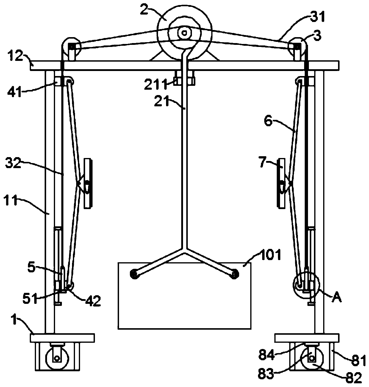
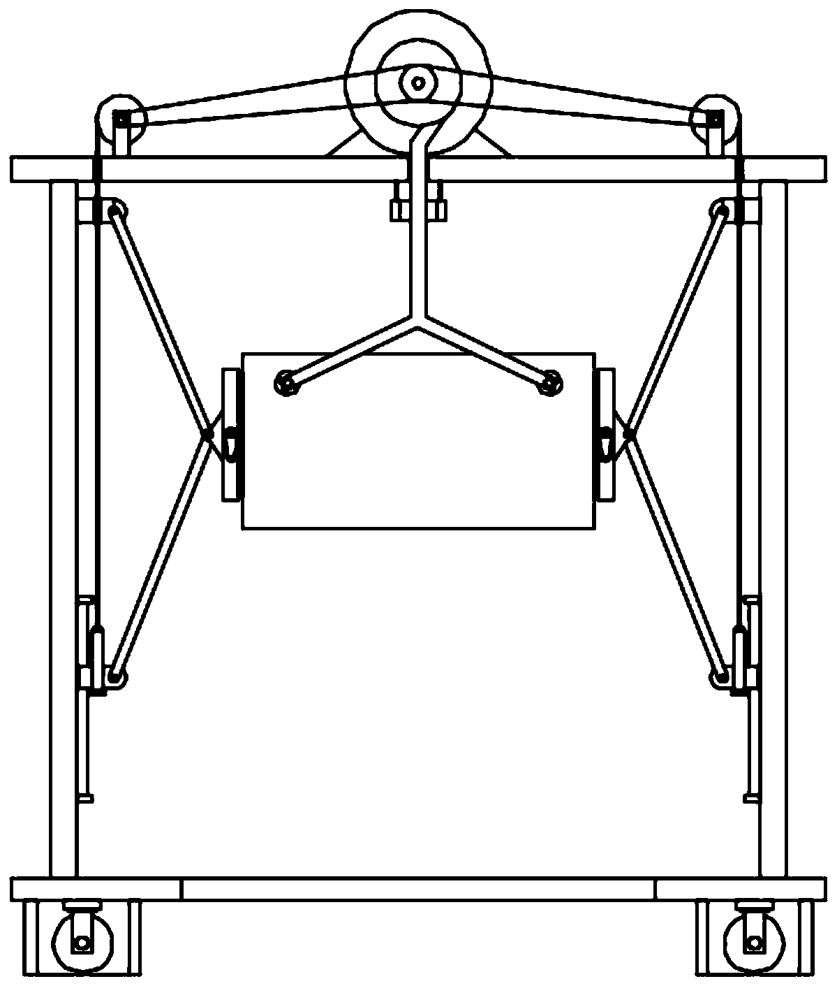
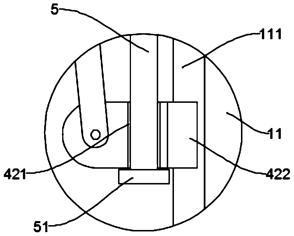
[0023] see Figure 1~5 , in an embodiment of the present invention, a material transfer device for coastal engineering construction, including two symmetrically arranged bases 1, a stand 11 fixed to the base 1, and a top plate 12 fixed to the top of the two stand 11, the base 1 The bottom is equipped with a walking mechanism; the top center of the top plate 12 is equipped with a hoist 2, and the reel of the hoist 2 is wound with a sling 21 for lifting the material box 101. During work, the material is loaded in the material box 101, and then Utilize the winch 2 to lift the material box 101, and then use the traveling mechanism to drive the material box 101 to move to the designated location to complete the transfer.

[0024] In order to better guide the suspension rope 21 , in this embodiment, a guide ring 211 is fixed at the center of the bottom of the top plate 12 , and the guide ring 211 is sleeved around the periphery of the suspension rope 21 .

[0025] The top of the to...

Embodiment 2

[0034] The embodiment of the present invention optimizes the design of the running mechanism on the basis of embodiment 1, specifically:

[0035]Described walking mechanism comprises support cover 81 and roller 82, and described support cover 81 is fixed on the bottom of base 1, and the inner cavity top of support cover 81 is equipped with lifting device, and the movable end of lifting device is fixed with mounting frame 83, and mounting frame 83 Roller 82 is installed on the upper rotation, and when the lifting device is in the maximum stroke position upwards, the roller 82 is located in the support sleeve 81, so that during the lifting process, the roller 82 can be hidden in the support sleeve 81, and the support sleeve 81 is directly in contact with the ground to ensure stability, and when it needs to move, the lifting device drives the roller 82 to move downwards and stretch out the support sleeve 81.

[0036] The specific structure of the lifting device is not limited. Pr...


PUM


Abstract

The invention discloses a material transferring device for coastal engineering construction. The device comprises a base, a vertical frame and a top plate, and a travelling mechanism is installed at the bottom of the base; a winch is mounted in the center position of the top of the top plate; a driven winding drum is mounted at the top of the top plate, and a traction rope is wound on the driven winding drum; a fixed seat and a movable seat are arranged on the inner side of the vertical frame; first connecting frames are hinged to the fixed seat and the movable seat, and clamping pieces are hinged to tail ends of the two first connecting frames; a free end of the traction rope sequentially penetrates through the fixed seat and the movable seat and is connected with a lifting rod, and an abutting block is fixed to the bottom of the lifting rod. By arranging the driven winding drum, the fixed seat, the movable seat, the first connecting frame and the clamping pieces, the material box canbe clamped and fixed by the symmetrically arranged clamping pieces while the winch lifts the material box, so that the material box is prevented from shaking in the moving process, and the working safety is improved.

Description

technical field [0001] The invention relates to the field of coastal engineering construction, in particular to a material transfer device for coastal engineering construction. Background technique [0002] During the construction of coastal engineering, it is necessary to transfer materials, that is, to transfer materials from one place to another, and a transfer device is needed to complete the above work. Most of the transfer devices in the prior art are similar to the driving style, that is, the materials are lifted from the ground first, and then transported. However, there is a problem in the use of this transfer device, that is, the materials that are lifted are easy to move due to inertia. The effect produces shaking, and there is a certain potential safety hazard. Contents of the invention [0003] The object of the present invention is to provide a material transfer device for coastal engineering construction to solve the above problems. [0004] To achieve the...

Claims


Application Information

Patent Timeline
Patent Type & Authority Applications(China)
IPC IPC(8): B66C5/02B66C13/06
CPCB66C5/02B66C13/06
Inventor 孙晓文
Owner 孙晓文
Why Eureka
Try Eureka