
Traffic deceleration strip device for extending deceleration

A speed bump, traffic technology, applied in traffic signals, roads, road signs, etc., can solve the problems of insufficient speed bump effect, dangerous vehicle slippage, unfavorable traffic driving, etc., so as to improve driving safety and reduce excessive traffic. The effect of bumping, reducing the speed of the vehicle

Active Publication Date: 2020-08-07
浙江融通环保科技有限公司
View PDF5 Cites 2 Cited by
  • Summary
  • Abstract
  • Description
  • Claims
  • Application Information

AI Technical Summary

Problems solved by technology

[0003] The deceleration effect of the traffic deceleration belt at the current stage is not significant enough, causing too much bumpy feeling. The deceleration effect of entering the deceleration zone is the same as leaving the deceleration zone, which is not conducive to traffic driving, and the sand brought by vehicles passing by will cause subsequent vehicles to skid Danger

Method used


Image

  • Traffic deceleration strip device for extending deceleration
  • Traffic deceleration strip device for extending deceleration
  • Traffic deceleration strip device for extending deceleration

Examples


Embodiment Construction

[0018] All the features disclosed in this specification, or all disclosed methods or steps in the process, except for mutually exclusive features and or steps, can be combined in any manner.

[0019] Combine below Figure 1-4 The present invention will be described in detail. For the convenience of description, the orientations mentioned below are now specified as follows: figure 1 The vertical, horizontal, front and rear directions of the projection relationship are the same.

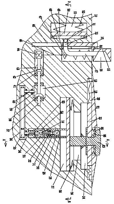
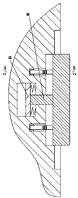
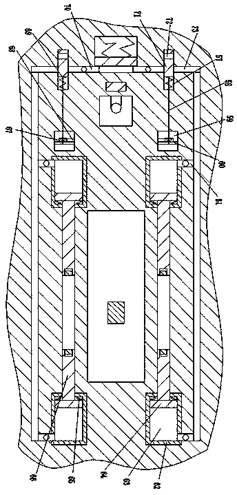
[0020] An extended decelerating traffic speed belt device of the device of the present invention includes a road 10, the top wall of the road 10 is provided with a first chute 20 with an upward opening, and the first chute 20 is symmetrically slidingly connected to the first The sliding block 22 is provided with a curved block 23 between the left and right first sliding blocks 22, and the first sliding block 22 passes through the first sliding groove 20 between the end wall away from the curved block 23 and...


PUM


Abstract

The invention discloses a traffic deceleration strip device capable of extending and decelerating. The device comprises a road, a first sliding groove with an upward opening is formed in the top wallof the road. First sliding blocks are slidably connected into the first sliding groove in a bilateral symmetry mode. A cambered surface block is arranged between the left and right first sliding blocks; the end wall, away from the cambered surface block, of the first sliding block is connected with the first sliding groove through a first spring; the top wall of the first sliding block is fixedlyprovided with a slope block slidably connected with the top wall of the road; a second sliding block is fixedly arranged on the bottom wall of the cambered surface block; second sliding grooves with openings back to the second sliding block are symmetrically formed in the left and right end walls of the cambered surface block; the second sliding groove is in sliding connection with the first sliding block. Third sliding grooves are formed in the bottom walls of the left-right first sliding grooves. Two fourth sliding grooves with upward openings are symmetrically formed in the bottom wall of the sliding shaft in the front-back direction, bumping buffer mechanisms are arranged in the fourth sliding grooves, buffer extending speed reducing mechanisms are symmetrically arranged on the left end walls and the right end walls of the fourth sliding grooves, the speed reducing section of the speed bump can be prolonged, the speed reducing effect of the traffic speed bump is enhanced, and subsequent vehicle slipping can be avoided.

Description

Technical field [0001] The invention relates to the related technical field of traffic speed bumps, in particular to a traffic speed bump device for extended speed reduction. Background technique [0002] Traffic speed bumps are also called deceleration ridges, which are traffic facilities installed on highways to slow passing vehicles. Generally, it is alternated with yellow and black to attract visual attention, and the road is slightly arched to achieve the purpose of vehicle deceleration. It is generally set at road crossings, industrial and mining enterprises, schools, residential communities and other road sections where vehicles need to slow down and road sections that are prone to traffic accidents. It is a new type of traffic-specific safety setting used to reduce the speed of motorized and non-motorized vehicles. [0003] At this stage, the deceleration effect of traffic deceleration belts is not significant enough, and the resulting turbulence is too large. The decelera...

Claims


Application Information

Patent Timeline
IPC IPC(8): E01F9/529
CPCE01F9/529
Inventor 徐浩
Owner 浙江融通环保科技有限公司
Learn More