Energy-saving power generation device for ship

A technology for energy-saving power generation and ships, applied to electromechanical devices, wind power generation, engines, etc., to achieve good deceleration effect, simple structure, and improved utilization efficiency

Inactive Publication Date: 2013-07-31
HARBIN ENG UNIV
View PDF8 Cites 6 Cited by
  • Summary
  • Abstract
  • Description
  • Claims
  • Application Information

AI Technical Summary

Problems solved by technology

This device is not suitable for ships, and this structure simply puts wind power generation and water flow power generation on one platform, and the two generate power separately. There is no research on the structure that combines the two power generation methods

Method used


Image

  • Energy-saving power generation device for ship
  • Energy-saving power generation device for ship
  • Energy-saving power generation device for ship

Examples


specific Embodiment approach 1

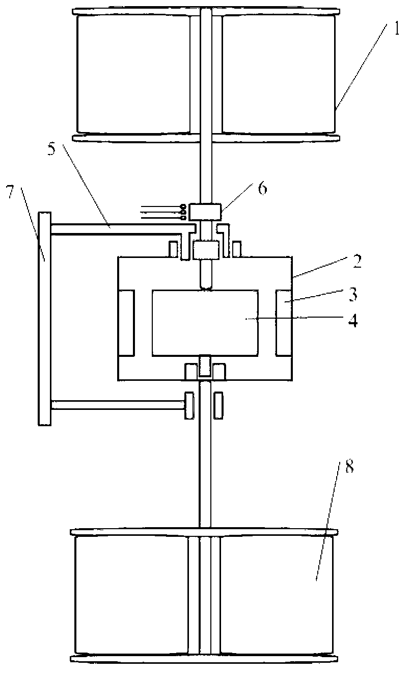
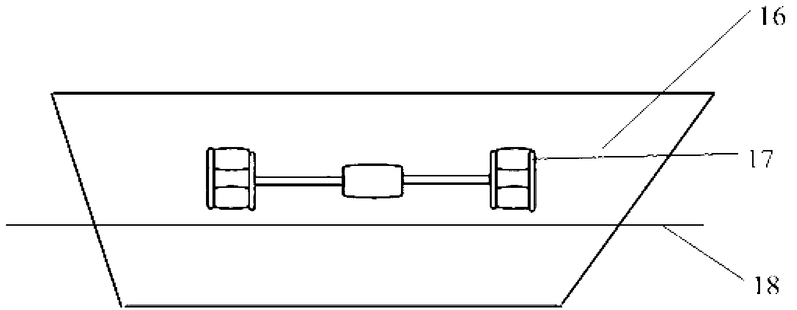
[0024] Specific implementation mode 1: see figure 1 , 3 4. This design mainly uses the structural characteristics of the dual-rotor generator, fully combines the advantages of wind power generation and water current power generation, and is mainly used when the ship is decelerating and stationary according to the characteristics of the ship when it is sailing. This generator can be installed in such image 3 , 4 In the shipboard position shown, when the ship sails normally, power generation is not required at this time, and the additional resistance brought by the power generation device to the ship's navigation needs to be minimized. When the power generation device is not working, the control mechanism controls the rotation of the turntable 7 so that the power generation device is in the image 3 In the position shown, the power generation device is in a horizontal state, the water turbine is out of the water, and the wind turbine and water turbine in the form of a vertic...

specific Embodiment approach 2

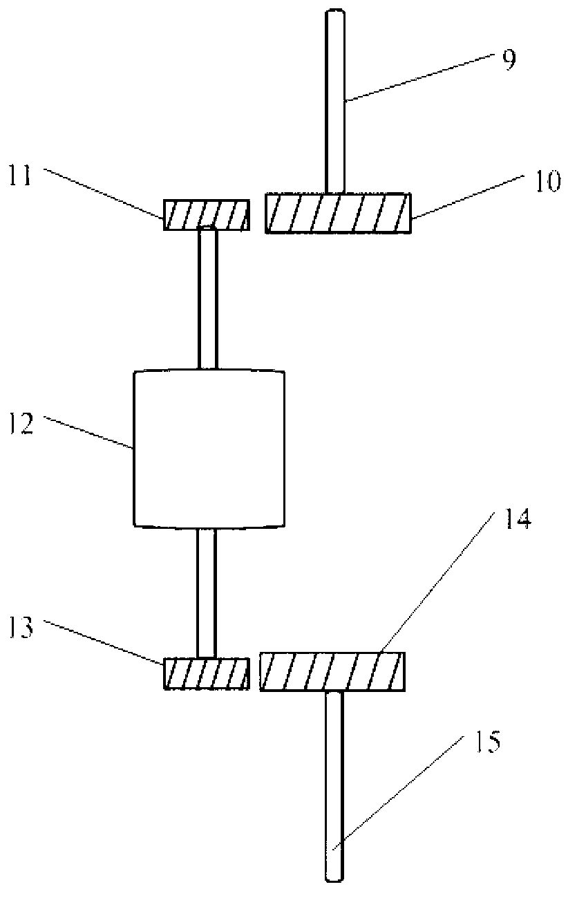
[0025] Specific implementation mode 2: see figure 1 , 2, 3, 4, the installation method of the power generation device is the same as that of the scheme 1. On the basis of the implementation mode 1, implementation mode 2 adds such as between the wind turbine and the generator and between the water turbine and the generator. figure 2 The gear speed increaser shown. figure 2 Middle 9 is the rotating shaft of the wind turbine, and 15 is the rotating shaft of the water turbine. Since the rotating speed of the wind turbine and the water turbine is relatively slow during work, the figure 2 The effect of the middle gear 10, the gear 11, the gear 13 and the gear 14 increases the rotating speed of the input generator 12. The generator obtains a higher rotating speed, the volume of the generator can be further reduced, and the output power can also be increased.

specific Embodiment approach 3

[0026] Specific embodiment 3: the power generation device in embodiment 1 and embodiment 2 all is to work under the ship deceleration or berthing state, in order to reduce the resistance of power generation device to ship navigation when ship sails normally, power generation device will not work. The situation during the ship's navigation is very complicated, and situations such as insufficient power supply of the power system may occur. The power generation device in the present invention can also be used as a conventional power generation device in the normal navigation of the ship. As long as the power generation device is fixed in the vertical direction through the control device when the ship is sailing normally, the power generation device can continuously supply power to the ship's power grid through the converter.


PUM


Abstract

The invention belongs to the field of energy-saving power generation device for a ship and particularly relates to a device for generating power by wind energy and water flow energy when the ship is in the static or speed reduction state. The energy-saving power generation device for the ship comprises a wind turbine, a dual-rotor power generator and a water turbine, wherein the wind turbine comprises blades and a wind turbine rotary shaft. The energy-saving power generation device combines the functions of wind power generation and water flow power generation through the dual-rotor power generator, is simple in structure, smaller in volume under the same power and easy to realize on the ship, makes full use of offshore wind energy, water flow energy and mechanical energy of the ship, reduces the ocean pollution when the traditional energy is used by the ship, and improves the utilization efficiency of the ship to the traditional energy. The power generation device is applied when the ship is in the speed reduction state, so that the excessive kinetic energy of the ship can be absorbed, a better speed reduction effect can be obtained, the speed reduction time of the ship is greatly shortened, and the speed reduction controllability is improved.

Description

technical field [0001] The invention belongs to the field of energy-saving power generation applied to ships, in particular to a power generation device utilizing wind energy and water current energy when the ship is stationary and decelerating. Background technique [0002] At present, the development of the shipbuilding industry is getting faster and faster, and the tonnage of ships is also increasing. The energy saving and emission reduction of ships is a problem worth studying. Most of the electricity used by ships now is to drive generators to generate electricity through the combustion of fuel, which will consume a lot of energy. However, the fuel that ships can carry is limited, and the storage capacity of these energy sources is also limited. These problems make us have to consider how to minimize the consumption of energy carried by ourselves during ship navigation. We know that there are various renewable energy sources in nature, such as wind energy and water flo...

Claims


Application Information

Patent Timeline
Patent Type & Authority Applications(China)
IPC IPC(8): F03B13/00F03D9/00H02K5/10
CPCY02E10/725Y02E10/72Y02A30/14
Inventor 程鹏秦鹏兰海张敬南黄曼磊刘宏达张强李纪辉李峰岩王庚
Owner HARBIN ENG UNIV
Why Eureka
Try Eureka