Automatic speed reducing device for rotating shaft

A rotating shaft, automatic technology, applied in the direction of brake types, drum brakes, brake actuators, etc., can solve the problems of personal injury, lack of protective devices, etc.

Active Publication Date: 2017-11-10
杭州腾飞链条管业有限公司
View PDF8 Cites 6 Cited by
  • Summary
  • Abstract
  • Description
  • Claims
  • Application Information

AI Technical Summary

Problems solved by technology

After the electric tool is processed, the rotating shaft on the electric tool needs to be stopped quickly to prevent the rotating shaft from continuing to drive the processing tool to rotate after the processing is completed, causing unnecessary personal and property damage, for example: cutting, milling, etc. by rot

Method used


Image

  • Automatic speed reducing device for rotating shaft
  • Automatic speed reducing device for rotating shaft

Examples


Embodiment Construction

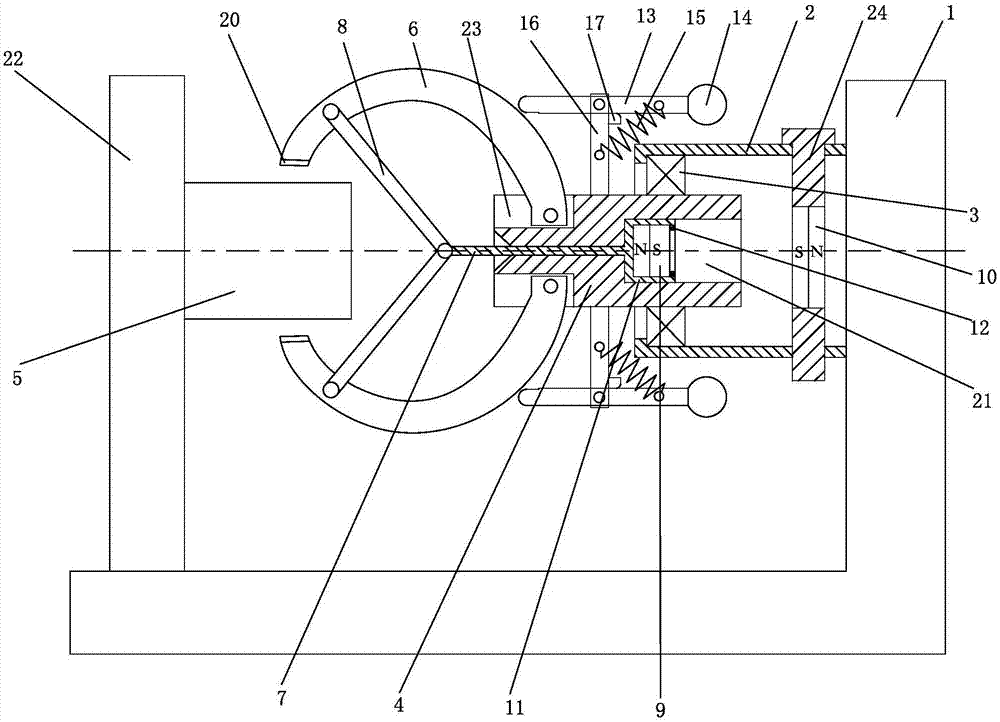
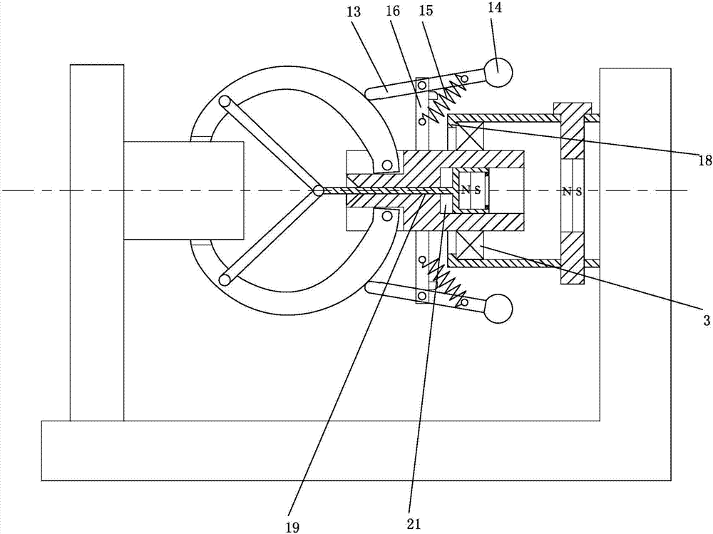
[0014] The present invention will be further described below with reference to the drawings and specific embodiments.

[0015] As shown in the figure, the device for automatic deceleration of a rotating shaft of the present invention includes a base 1, which can be connected with an electric tool 22, a guide sleeve 2 is provided on the base 1, and the guide sleeve 2 is rotatably connected through a bearing 3. Cylinder 4, a plurality of claws 6 are connected to the end of the cylinder 4 to rotate towards the shaft 5, the rotation shaft 5 is the output end of the electric tool 22, and the claws 6 are evenly distributed around the axis of the cylinder 4; the cylinder 4 is slidingly connected There is a pull rod 7, one end of the pull rod 7 close to the rotating shaft 5 is provided with a connecting rod 8 for driving a plurality of claws 6 to rotate synchronously, a first magnet 9 is provided on the end of the pull rod 7 away from the rotating shaft 5, and an end of the guide sleeve 2...


PUM


Abstract

The invention discloses an automatic speed reducing device for a rotating shaft. The device comprises a base (1), wherein the base (1) is provided with a guide sleeve (2), the guide sleeve (2) is rotationally connected with a cylinder (4) through a bearing (3), the end, facing a rotating shaft (5), of the cylinder (4) is rotationally connected to a plurality of claws (6), and the plurality of claws (6) are evenly distributed around the axis of the cylinder (4); a pull rod (7) is slidably connected to the cylinder (4), the end, close to the rotating shaft (5) , of the pull rod (7) is provided with connecting rods (8) for driving the plurality of the claws (6) to rotate synchronously, and the end, far away from the rotating shaft (5), of the pull rod (7) is provided with a first magnet (9); and the end, far away from the cylinder (4), of the guide sleeve (2) is rotationally connected to a rotating pin (24), and a second magnet (10) which is used for attracting or repelling the first magnet (9) is arranged in the rotating pin (24) in an embedded mode. According to the automatic speed reducing device for the rotating shaft, the rotating shaft can automatically stop rotating after the work is finished.

Description

Technical field [0001] The invention relates to a device for automatically decelerating a rotating shaft. Background technique [0002] In the machining process, power tools are usually used, and the power tools output rotary motion to process the workpiece. After the power tool is processed, the rotating shaft on the power tool needs to be stopped quickly to prevent the rotating shaft from continuing to drive the processing tool to rotate after the processing is completed, causing unnecessary personal and property damage, for example: cutting, milling, etc. through the rotating tool When machining is completed, the tool should be stopped as soon as possible after the processing is completed; for example, electric saws, electric screwdrivers, etc., these rotating shafts need to be stopped as soon as possible after the work is completed, but due to the lack of protection devices, it is easy to cause unnecessary personal injury. Summary of the invention [0003] The technical probl...

Claims


Application Information

Patent Timeline
IPC IPC(8): F16D49/00F16D49/18F16D65/18F16D121/20
CPCF16D49/00F16D49/18F16D2121/20
Inventor 王东来
Owner 杭州腾飞链条管业有限公司
Why Eureka
Try Eureka