
High embankment slope stabilizing structure and construction method thereof

A technology for stabilizing structures and embankments, applied in infrastructure engineering, underwater structures, roads, etc., can solve the problems of difficult to control operation safety, relatively limited site conditions, and single reinforcement methods, so as to reduce the risk of stagnant water collapse. , The effect of reducing the grading range and reducing the thickness of the building

Active Publication Date: 2020-08-07
ZHEJIANG UNIV CITY COLLEGE
View PDF4 Cites 6 Cited by
  • Summary
  • Abstract
  • Description
  • Claims
  • Application Information

AI Technical Summary

Problems solved by technology

[0005] The purpose of the present invention is to provide a high embankment slope stability structure and construction method to solve the main problems in the existing anti-slip reinforcement technology of high embankments near mountains, such as poor reinforcement effect, relatively limited by site conditions, difficult drainage, and construction problems. Problems such as high cost, single reinforcement method, and difficult control of post-operation security

Method used


Image

  • High embankment slope stabilizing structure and construction method thereof
  • High embankment slope stabilizing structure and construction method thereof
  • High embankment slope stabilizing structure and construction method thereof

Examples


Embodiment Construction

[0048] The present invention will be further described below in conjunction with the examples. The description of the following examples is provided only to aid the understanding of the present invention. It should be pointed out that for those skilled in the art, without departing from the principle of the present invention, some improvements and modifications can be made to the present invention, and these improvements and modifications also fall within the protection scope of the claims of the present invention.

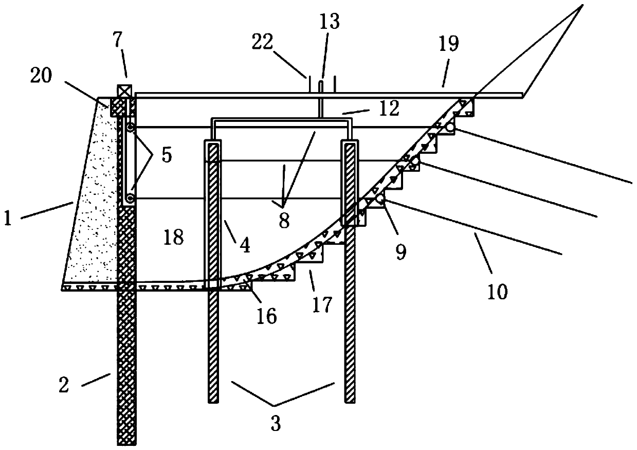
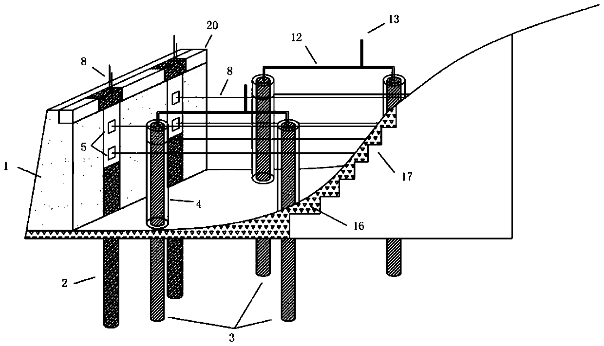
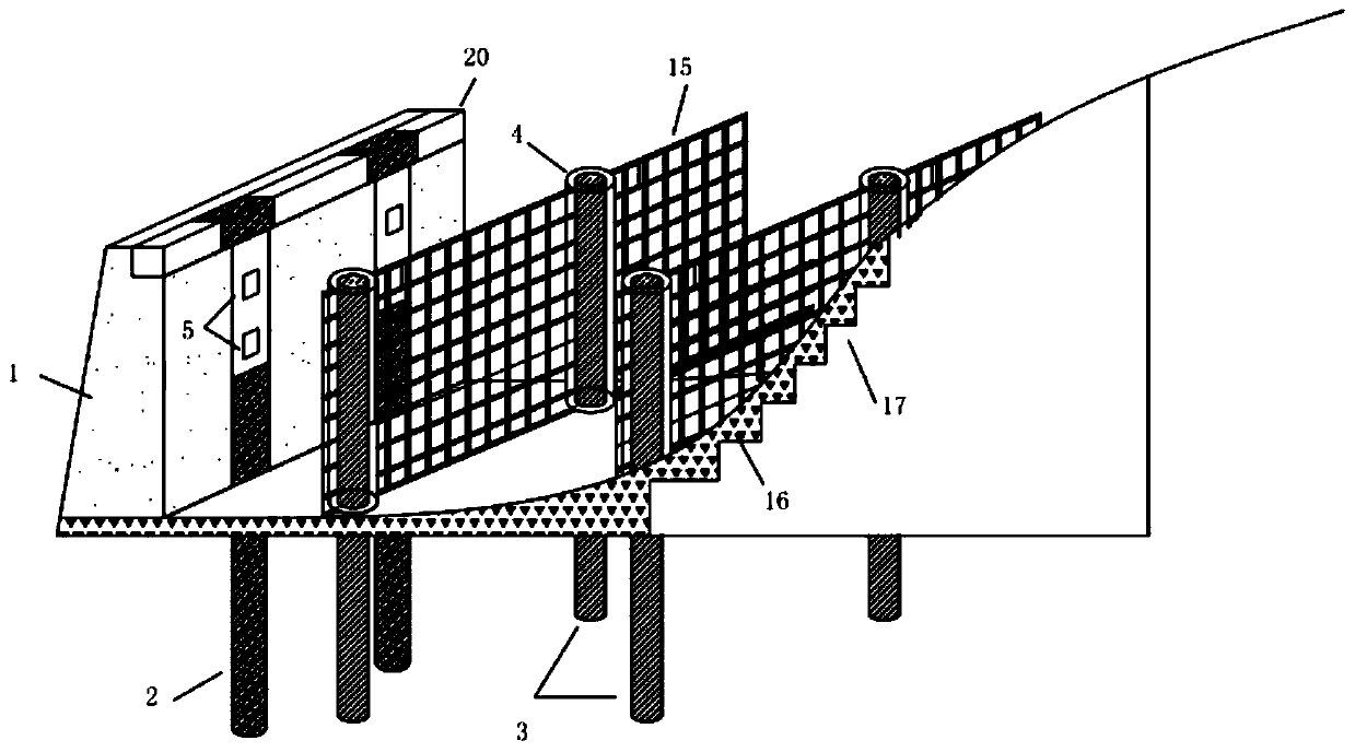
[0049] Such as Figure 1-8 As shown, the present embodiment provides a high embankment slope stabilization structure, comprising: a retaining wall 1, steel pipe piles 3 and anchor rods 10; A steel pipe concrete pile 2 is installed adjacent to the inner surface, and the top of the steel pipe concrete pile 2 is connected with a crown beam 20. The step 17, the surface of the excavation step 17, the bottom of the retaining wall 1 and the surface of the base of the e...


PUM


Abstract

The invention discloses a high embankment slope stabilizing structure. The high embankment slope stabilizing structure comprises a retaining wall, steel pipe piles and anchor rods; the retaining wallis arranged at the foot of a high embankment slope, concrete-filled steel pipe piles are arranged on the inner surface of the retaining wall, an excavation step and a gravel drainage zone are arrangedat a filling and excavation interface, the bottoms of the concrete-filled steel pipe piles and the steel pipe piles penetrate through the gravel drainage zone, and the upper sections of the steel tube piles are sleeved with grouting sleeves correspondingly; the lower end of the grouting sleeves extend to the gravel drainage zone, the upper end of each grouting sleeve is connected with a groutingopening through a grouting pipe, a fixed pulley and a pipeline channel are arranged inside each concrete-filled steel pipe pile, the anchor rods are is fixed in a rock stratum behind the excavation step, the exposed parts of the tops of the anchor rods are connected with steel strands, and the steel strands are connected to the fixed pulleys or the steel pipe piles at the same height; the steel strands connected to the fixed pulleys are led out of crown beam through the pipeline channel and connected with a steel strand tensioning device. The high embankment slope stabilizing structure is suitable for reinforcing and active control of embankment deformation in the embankment construction and operation process, and is particularly suitable for embankment projects with high requirements forembankment stability and later operation safety.

Description

technical field [0001] The invention belongs to the technical field of embankment engineering reinforcement and protection, and in particular relates to a high embankment slope stabilization structure and construction method, which is suitable for reinforcement and active control of embankment deformation during embankment construction and operation, especially for embankment stability and later operation safety It is especially suitable for embankment projects with high requirements. Background technique [0002] Half-fill and half-cut highway embankment is a common construction method in the process of road construction in mountainous areas. Due to the large difference in mechanical properties between the embankment filling material and the rock and soil on the slope surface of the mountain, slippage easily occurs at the interface between filling and excavation. To cause safety accidents such as embankment collapse, certain measures must be taken for reinforcement during t...

Claims


Application Information

Patent Timeline
IPC IPC(8): E02D17/20E02D29/02E02D5/28E02D5/38E02D5/74E01C3/00E02D3/10
CPCE01C3/00E02D3/10E02D5/285E02D5/38E02D5/74E02D17/207E02D29/0275
Inventor 蒋吉清吴熙齐永洁周联英
Owner ZHEJIANG UNIV CITY COLLEGE
Learn More