Overflow valve for improving overflow capability

An overflow valve and overflow technology, which is applied in the field of sanitary ware, can solve the problems of reducing drainage speed, etc., and achieve the effects of improving overflow capacity, stable flow, and large flow area

Pending Publication Date: 2020-08-07
谷力(厦门)科技有限公司
View PDF0 Cites 0 Cited by
  • Summary
  • Abstract
  • Description
  • Claims
  • Application Information

AI Technical Summary

Problems solved by technology

When the drain valve is opened, the water flows out through the drain port of the drain valve base. During normal use, since the drain port of the drain valve base communicates with the outside air through the overflow pipe channel, when draining, a negative pressure will be generated in the drain channel, and the outside world will Under the action of atmospheric pressure, the air will be mixed into the drain outlet of the drain valve base, so that the drain channel is not full of water, thereby reducing the draining speed

Method used


Image

  • Overflow valve for improving overflow capability
  • Overflow valve for improving overflow capability
  • Overflow valve for improving overflow capability

Examples


Embodiment 1

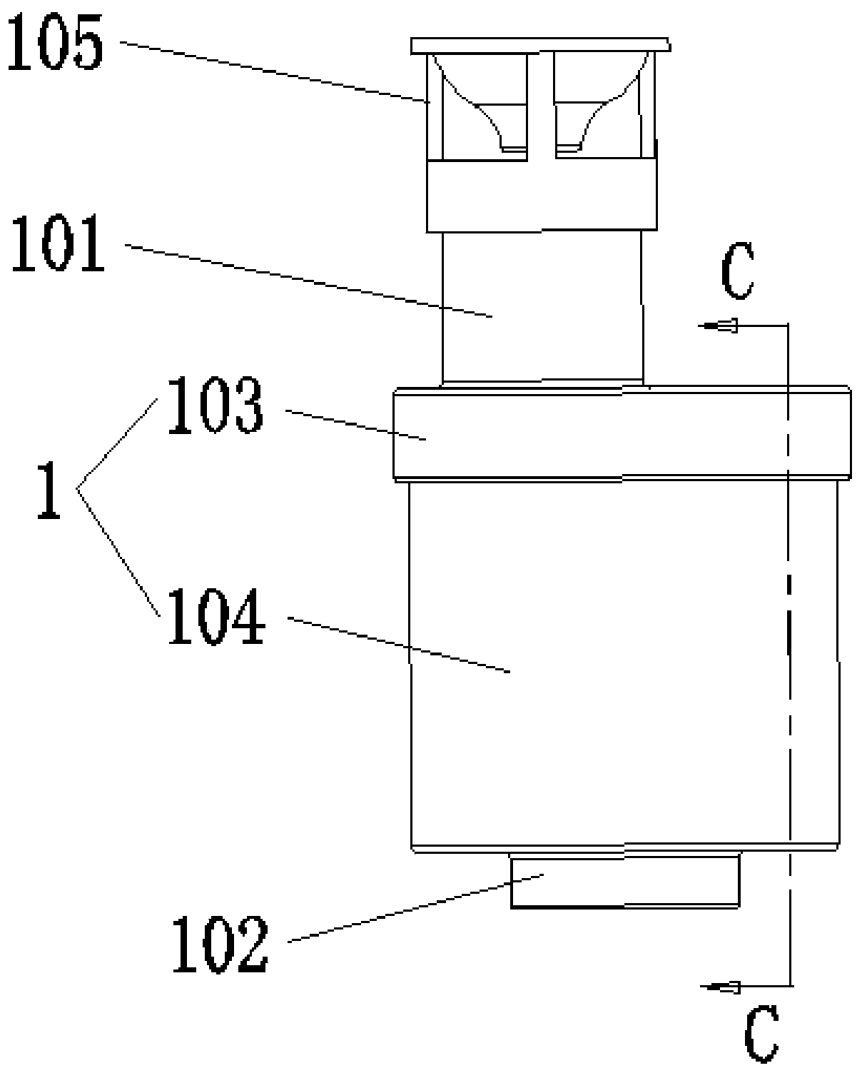
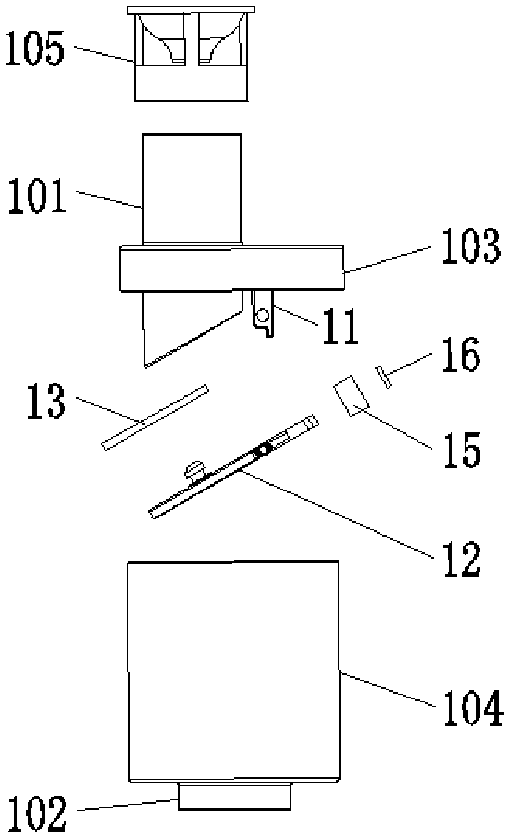
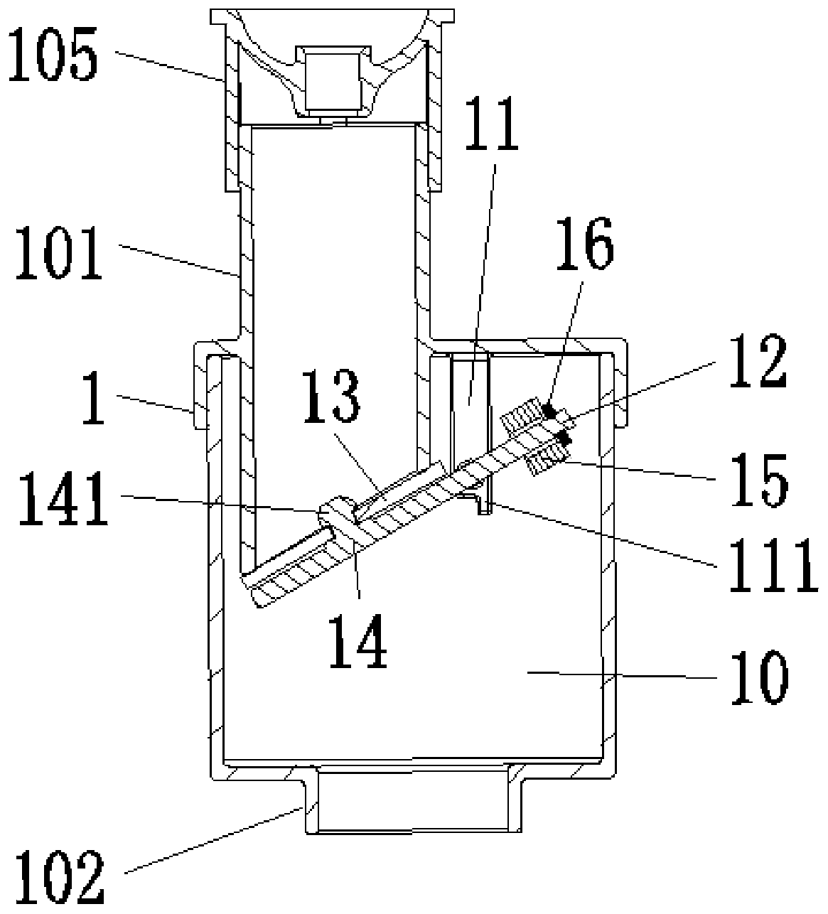
[0046] Such as Figure 1-7 As shown, an overflow valve with improved overflow capacity includes a casing 1, a cavity 10 is opened inside the casing 1, and an inlet pipe 101 and an outlet pipe 102 communicating with the cavity 10 are respectively provided on the top and bottom of the casing 1. . The bottom of the water inlet pipe 101 extends into the cavity 10, and the top wall of the cavity 10 is fixed with a support member on the side of the water inlet pipe 101. The support member includes two connecting plates 11 arranged in parallel and spaced apart from each other. The connecting plate 11 is provided with Positioning hole 110. The bottom of support is hinged with a lever guide post 12, and the both sides of lever guide post 12 extend outwards respectively to form two positioning rods 120, and two positioning rods 120 are hinged with the positioning holes 110 on the two connecting plates 11 respectively.

[0047]One end of the lever guide post 12 is fixedly provided with...

Embodiment 2

[0054] Such as figure 1 , Figure 13 , Figure 14 As shown, the difference between this embodiment and Embodiment 1 is that the balance structure is a spring 17, and the top wall of the cavity 10 is fixedly provided with a support rod 18 on the side of the support member, and the bottom of the support rod 18 is lower than the lever. A horizontal plate 19 is fixed at the position of the fulcrum of the guide post 12 . The lower end of the spring is fixed on the cross plate 19, and the upper end is connected with the bottom of the lever guide post 12 and is in a stretched state. The rest of the structure of this embodiment is the same as that of Embodiment 1.

[0055] Such as Figure 15 As shown, under normal circumstances, the lever guide post 12 is due to the pulling force of the spring 17, the moment M1 produced by the spring 17 is greater than the moment M2 at the other end of the lever guide post 12, and the lever guide post 12 is in a closed state ( Figure 15 a); when...

Embodiment 3

[0057] Such as figure 1 , Figure 16 , Figure 17 As shown, the difference between the present embodiment and the first embodiment is only that the sealing end surface at the bottom of the water inlet pipe 101 is a horizontal plane, and the rest of the structure of this embodiment is the same as that of the first embodiment.

[0058] Such as Figure 18 As shown, under normal circumstances, the lever guide post 12 is due to the gravity effect of the counterweight 15, the moment M1 of the counterweight 15 is greater than the moment M2 of the other end of the lever guide post 12, and the lever guide post 12 is in a closed state ( Figure 18 a); when the sealing rubber pad 13 is subjected to an external force, and the moment M4 is greater than the counterweight moment M3, the lever guide post 12 is opened ( Figure 18 b). The remaining installation methods and realized functions of this embodiment are the same as those of Embodiment 1.


PUM


Abstract

The invention discloses an overflow valve for improving the overflow capability. A shell is included and internally provided with a cavity. A water inlet pipe and a water outlet pipe are arranged at the top and the bottom of the shell correspondingly, and the bottom of the water inlet pipe stretches into the cavity. The part, on the side edge of the water inlet pipe, of the top wall of the cavityis fixedly provided with a supporting piece. A lever guide column is hinged to the lower portion of the supporting piece. A seal rubber pad which is in seal fit with the bottom of the water inlet pipeis fixedly arranged at one end of the lever guide column, and the other end is provided with a balance structure body used for forming lever balance with the seal rubber pad and driving the seal rubber pad to upwards reset. In the normal situation, the seal rubber pad seals and closes the water inlet pipe under the action of the balance structure body, and when a drain valve discharges water, outside air cannot enter a water outlet of the drain valve from the water inlet pipe, and the water discharging speed is greatly increased through the siphonic effect; and when the water pressure exertedon the seal rubber pad is higher than the acting force of the balance structure body, the lever guide column drives the seal rubber pad to rotate, the water inlet pipe is opened, the overflow valve achieves the overflow function, and the overflow effect is good.

Description

technical field [0001] The invention relates to the field of sanitary ware, in particular to an overflow valve with improved overflow capacity. Background technique [0002] Existing drain valve is made of valve body, base, overflow pipe. Wherein, the valve base communicates with the overflow pipe. Under the normal water-stop state, the outside air communicates with the drain port of the drain valve base through the overflow pipe. When an overflow occurs, water flows from the overflow pipe to the drain at the base of the drain valve and into the toilet pipe. When the drain valve is opened, the water flows out through the drain port of the drain valve base. During normal use, since the drain port of the drain valve base communicates with the outside air through the overflow pipe channel, when draining, a negative pressure will be generated in the drain channel, and the outside world will Under the action of atmospheric pressure, air will be mixed into the drain outlet of t...

Claims


Application Information

Patent Timeline
IPC IPC(8): F16K17/04F16K17/12E03D1/34
CPCE03D1/34F16K17/0413F16K17/12
Inventor 陈雪瑜
Owner 谷力(厦门)科技有限公司
Why Eureka
Try Eureka