Household decoration pipeline sealing device convenient for subsequent clearing

A pipe sealing and household technology, applied in cleaning methods and appliances, pipe components, engine lubrication, etc., can solve the problems of cost, inconvenient cleaning, etc., and achieve the effects of reducing manual intervention, comprehensive lubrication, and reducing frictional resistance

Active Publication Date: 2020-08-07
广州珠江建筑装饰有限公司
View PDF14 Cites 3 Cited by
  • Summary
  • Abstract
  • Description
  • Claims
  • Application Information

AI Technical Summary

Problems solved by technology

[0003] In order to overcome the above-mentioned defects of the prior art, an embodiment of the present invention provides a pipe sealing device for household decoration that is convenient for subsequent cleaning. The technical problem to be solved by the present invention is: the traditional processing method consumes a certain amount of newspapers, and subsequent cleaning is inconvenient

Method used


Image

  • Household decoration pipeline sealing device convenient for subsequent clearing
  • Household decoration pipeline sealing device convenient for subsequent clearing
  • Household decoration pipeline sealing device convenient for subsequent clearing

Examples


Embodiment 1

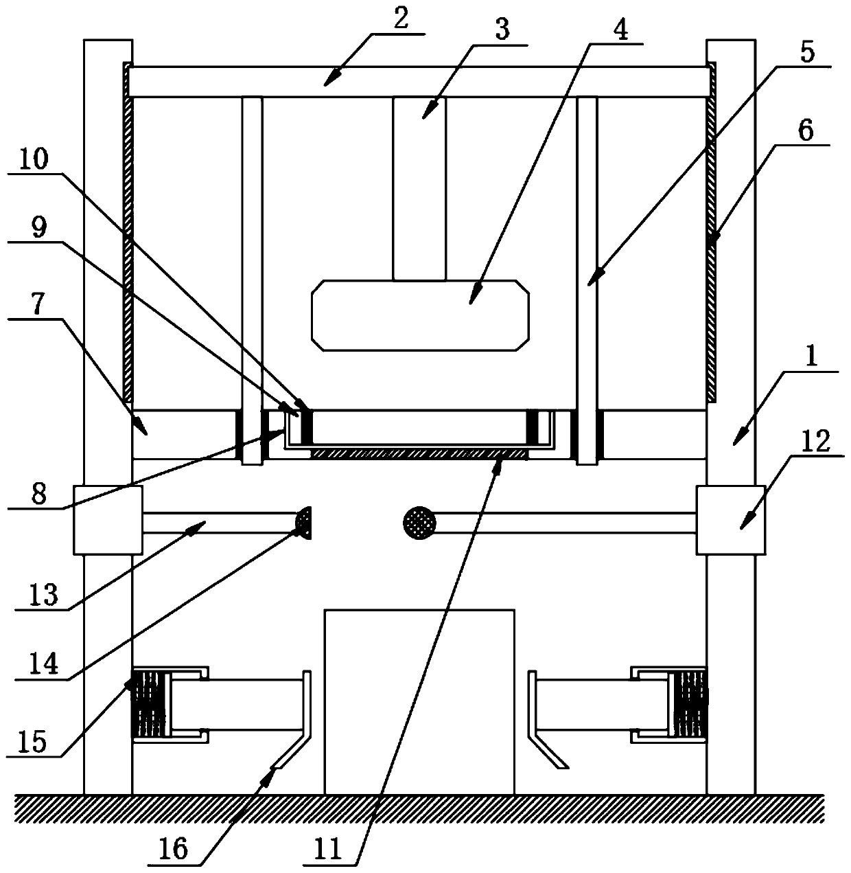
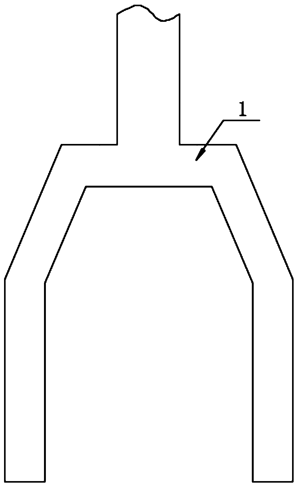
[0026] Such as Figure 1-2 As shown, the present invention provides a pipe sealing device for household decoration that is convenient for subsequent cleaning, including two vertically symmetrical brackets 1, and the brackets 1 are inverted Y-shaped structures, and the inner sides of the upper parts of the two brackets 1 There is a push mechanism between them, the push mechanism includes a horizontal plate 2, the bottom center of the horizontal plate 2 is fixedly connected with a push rod 3, the bottom end of the push rod 3 is fixed with a sponge block 4, and the horizontal plate on both sides of the push rod 3 2 The bottoms are fixedly connected with guide rods 5, and the inner upper parts of the two brackets 1 are provided with guide grooves 6, and the left and right ends of the horizontal plate 2 are slidably connected inside the corresponding guide grooves 6, and the bottom of the pushing mechanism is provided with a lubrication mechanism , the lubricating mechanism include...

Embodiment 2

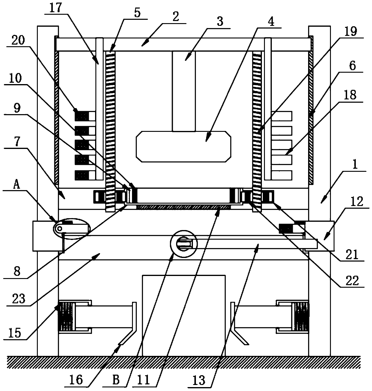
[0031] Such as Figure 3-8 As shown, different from Embodiment 1, the outer peripheral surface of the guide rod 5 is provided with threads 19, the two sides of the slot 8 are provided with grooves 21, the inside of the groove 21 is provided with a gear 22, and the bottom end of the guide rod 5 Through the center position of the gear 22, and threaded with the gear 22, the gear 22 is rotatably installed inside the groove 21, the outer peripheral surface of the ring 9 is provided with gear teeth, and the gear 22 is meshed with the ring 9 provided with the gear teeth on the outer peripheral surface ;

[0032] The front and rear sides of the horizontal plate 2 are provided with struts 30, and the struts 30 are arranged in a V shape, and the two struts 30 are arranged symmetrically about the center of the horizontal plate 2, and the two ends of the struts 30 arranged in a V shape Both are fixedly connected with vertical rods 17, and the outer lower part of the vertical rods 17 is e...


PUM


Abstract

The invention discloses a household decoration pipeline sealing device convenient for subsequent clearing, and particularly relates to the field of household decoration auxiliary devices. The device comprises two supports which are vertically and symmetrically arranged, the supports are of inverted Y-shaped structures, a pushing mechanism is arranged between the top ends of the two supports, the pushing mechanism comprises a transverse plate, a pushing rod is fixedly connected to the center of the bottom of the transverse plate, and a sponge block is fixedly arranged at the bottom end of the pushing rod. According to the device, by means of linkage between the pushing mechanism and a lubricating mechanism, in the downward moving process of the sponge wiping block, the pushing mechanism drives the lubricating mechanism to rotate to perform lubricating wiping on the sponge wiping block passing through the lubricating mechanism; and meanwhile, through linkage between a clearing mechanismand the pushing mechanism, when the pushing mechanism is pushed downwards, the clearing mechanism does not operate, and when the pushing mechanism is pulled upwards, the pushing mechanism drives the clearing structure to operate to beat the sponge block to clear building chippings attached to the top of the sponge block.

Description

technical field [0001] The invention relates to the field of home decoration auxiliary equipment, and more specifically, the invention relates to a home decoration pipe sealing device which is convenient for subsequent cleaning. Background technique [0002] In home decoration, a lot of pipes are often reserved for the convenience of subsequent decoration. If these long pipes are directly exposed to the outside world, it is easy to cause decoration waste to fall into the pipes, causing blockage and inconvenience for subsequent cleaning. However, the existing processing method is to directly use newspapers to block the pipe opening. This method needs to consume a certain amount of newspapers. At the same time, the insertion process consumes more manpower and material resources, and the subsequent cleaning is also relatively inconvenient. Contents of the invention [0003] In order to overcome the above-mentioned defects of the prior art, an embodiment of the present inventi...

Claims


Application Information

Patent Timeline
Patent Type & Authority Applications(China)
IPC IPC(8): F16L55/11F16N15/00B08B7/02
CPCF16L55/1141F16N15/00B08B7/02
Inventor 黎志洋
Owner 广州珠江建筑装饰有限公司
Why Eureka
Try Eureka