Indoor positioning method based on single-line laser radar

A single-line laser radar and indoor positioning technology, which is applied in the direction of electromagnetic wave re-radiation, radio wave measurement system, measuring device, etc., can solve the problems of inconvenient use, difficult to achieve centimeter-level indoor positioning accuracy, and inability to apply positioning accuracy. The effect of precision indoor positioning

Active Publication Date: 2020-08-07
中振同辂(江苏)机器人有限公司
4 Cites 1 Cited by

AI-Extracted Technical Summary

Problems solved by technology

[0003] Since it is difficult to receive satellite signals indoors, positioning methods such as GPS cannot quickly and accurately locate indoors, so other sensors are generally used for indoor positioning. Currently, common indoor positioning solutions include Wifi, Bluetooth, RFID, etc., but these positioning me...

Abstract

The invention discloses an indoor positioning method based on a single-line laser radar. The indoor positioning method comprises the following steps of (1) constructing an occupied grid map by using data acquired by the single-line laser radar, (2) constructing a local map by adopting the method in the step (1), and carrying out local matching, (3) constructing a global map by adopting the methodin the step (1), and carrying out global matching, (4) when a primary global matching result is obtained, constraining the global map and the local map on the timestamp of the global matching result and adding into an optimization queue, and in order to avoid accidental errors, performing least square optimization once when the optimization queue reaches a certain number, updating the historical positioning track in the current local map, and updating the pose of each point to finally obtain a real-time and accurate pose. According to the indoor positioning method based on the single-line laser radar, high-precision indoor positioning of various scenes can be achieved, and large support is provided for stable operation and work of a robot.

Application Domain

Navigational calculation instrumentsElectromagnetic wave reradiation

Technology Topic

Global MapReal-time computing +7

Image

  • Indoor positioning method based on single-line laser radar
  • Indoor positioning method based on single-line laser radar
  • Indoor positioning method based on single-line laser radar

Examples

  • Experimental program(1)

Example Embodiment

[0027] The technical scheme of the present invention will be further explained below in conjunction with the drawings.
[0028] The foregoing indoor positioning method based on single-line lidar includes the following steps:
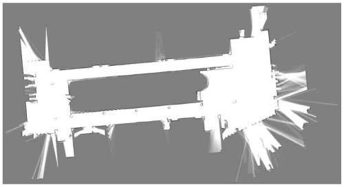
[0029] (1) Use the data collected by the single-line lidar to construct an occupation grid map. The single-line lidar will emit a laser beam in a fixed direction, and the emitted laser will be reflected when encountering obstacles. With the received time difference, the distance from the single-line lidar to the nearest obstacle in the direction can be calculated.
[0030] In the occupancy grid map, for a point, p(s=0) is used to indicate the probability that it is an empty state, and p(s=1) is used to indicate the probability that it is an occupied state, and the sum of the two is 1. The ratio of the two is introduced here as the state of the point: Odd(s)=p(s=1)/p(s=0). In the occupancy grid map, the larger the value of a point state, the more certain it is in the occupied state. On the contrary, the smaller the value, the more certain it is empty; for a point, if a new measurement value z appears, The state needs to be updated, that is, the state of s under the condition that the measured value z occurs, and the occupied grid map is constructed through continuous updating. Using the single-line lidar data, the occupation grid map established on a certain floor by the above method is as follows: figure 1 As shown, the darker the color, the greater the probability of obstacles appearing, and the lighter the color, the smaller the probability of obstacles appearing.
[0031] Considering computing resources and real-time performance, the matching problem is divided into two sub-problems: local positioning and global positioning. Local positioning is a positioning problem during the traveling of the robot in a relatively short period of time, that is, the pose at the previous moment is known, and the pose at the current moment is estimated in the local map. Since the errors of local positioning will accumulate, it is necessary to assist global positioning to continuously correct the offset and reduce the error. The local matching algorithm can be understood as the matching between the two measured values ​​before and after, the global matching algorithm is the matching between the current measured value and the global map. Local matching is real-time but there is error accumulation; global matching is time-consuming but high in accuracy, which can eliminate accumulated errors.
[0032] (2) Use the method in step (1) to construct a local map and perform local matching; the local map always retains data within a certain range. As the robot moves, the local map will be continuously updated, and new local map data will be generated at the same time Discard the old local map data.
[0033] Set the current measurement data as Use spatial transformation functions Means will do The matching problem can be transformed into a maximum likelihood function:
[0034]
[0035] In formula (1), p is the probability density function, which is obtained by rasterizing the measured data at the previous moment, and then calculating the multidimensional normal distribution of each grid; formula (1) can be equivalent to:
[0036]
[0037] In formula (2), the current measurement data Find the corresponding grid point for each data point of, and substitute it into the probability density function p for calculation, and use the Newton method to iteratively solve the equation (2) until convergence; when it converges, the maximum likelihood is obtained Function case Find the spatial transformation The pose at the current moment can be calculated from the pose at the previous moment, and the local positioning is completed.
[0038] (3) Use the method in step (1) to construct a global map and perform global matching; this mapping process builds a map covering the entire scene.
[0039] On the basis of the global map, construct multiple structural maps of different resolutions from coarse to fine:
[0040] (a) Rotate the measurement data clockwise by 0~360°, the specific angular resolution needs to be selected according to the actual situation to obtain the new measurement data under different rotation angles;
[0041] (b) Rasterize the measurement data under different rotation angles according to multiple resolutions, and use these rasterized data as candidates;
[0042] (c) Take the structure map with the lowest resolution, and translate the candidate from the origin at a certain step size at that resolution; continue to match the data obtained after translation with the structure map (the matching method is the same as the local matching method ), until the data obtained after translation is higher than the pre-set credibility threshold, the data is used as the candidate after screening;
[0043] (d) Perform the same strategy matching between the selected candidates and the higher-resolution structure map until the translation value and rotation value with the highest reliability at the highest resolution are obtained, which is the pose result obtained from the matching.
[0044] (4) Every time a global matching result is obtained, the global map and the local map are constrained on the timestamp of the global matching result and added to the optimization queue; to avoid accidental errors, a least squares is performed when the optimization queue reaches a certain number Optimize, update the historical positioning trajectory in the current local map, and update the pose of each point to finally obtain a real-time accurate pose.
[0045] reference figure 2 As shown, the continuous curve is the position trajectory of the robot obtained by the algorithm of the present invention, and the point trajectory is the real position point trajectory measured by the high-precision measuring instrument. It can be seen that the positioning result of the algorithm of the present invention is in good agreement with the actual position.
[0046] The above-mentioned embodiments are only to illustrate the technical concept and features of the present invention, and their purpose is to enable those familiar with the technology to understand the content of the present invention and implement it, and cannot limit the scope of protection of the present invention. All equivalent changes or modifications made by the essence should be covered by the protection scope of the present invention.

PUM

no PUM

Description & Claims & Application Information

We can also present the details of the Description, Claims and Application information to help users get a comprehensive understanding of the technical details of the patent, such as background art, summary of invention, brief description of drawings, description of embodiments, and other original content. On the other hand, users can also determine the specific scope of protection of the technology through the list of claims; as well as understand the changes in the life cycle of the technology with the presentation of the patent timeline. Login to view more.

Similar technology patents

Indoor positioning method based on intelligent mobile terminal with sound ranging function

InactiveCN106154230AHigh-precision indoor positioningGood scalability
Owner:ZHEJIANG UNIV

4D endogenous safety indoor positioning method based on intelligent metasurface and positioning system thereof

PendingCN114423077AHigh-precision indoor positioningRealize real-time positioning
Owner:CHINA ELECTRONICS TECH GRP NO 7 RES INST

Classification and recommendation of technical efficacy words

  • High-precision indoor positioning

Indoor positioning method based on intelligent mobile terminal with sound ranging function

InactiveCN106154230AHigh-precision indoor positioningGood scalability
Owner:ZHEJIANG UNIV

4D endogenous safety indoor positioning method based on intelligent metasurface and positioning system thereof

PendingCN114423077AHigh-precision indoor positioningRealize real-time positioning
Owner:CHINA ELECTRONICS TECH GRP NO 7 RES INST
Why Eureka
Try Eureka