Equipment fault alarm method and device

A technology for equipment failure and equipment to be tested, applied in alarms, measuring devices, instruments, etc., can solve problems such as low fault alarm accuracy, achieve high fault alarm accuracy, improve fault alarm accuracy, and be prone to early failures. Effect

Inactive Publication Date: 2020-08-07
郑州恩普特科技股份有限公司
View PDF6 Cites 3 Cited by
  • Summary
  • Abstract
  • Description
  • Claims
  • Application Information

AI Technical Summary

Problems solved by technology

[0007] The purpose of the present invention is to provide a method and device for equipment failure alarm to solve the problem of low accuracy of failure alarm for equipment failure alarm using vibration alarm standards provided by international or national standardization organizations

Method used


Image

  • Equipment fault alarm method and device
  • Equipment fault alarm method and device
  • Equipment fault alarm method and device

Examples


Embodiment approach 1

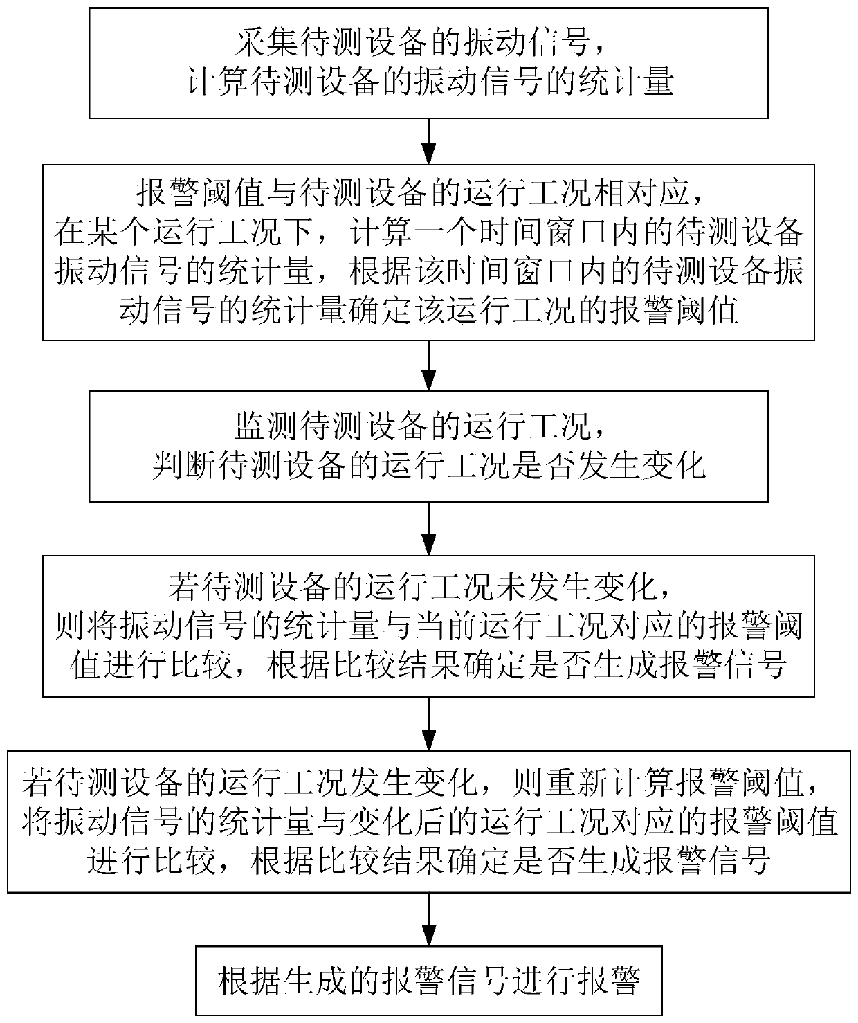
[0031] Embodiment 1 relates to an embodiment of an equipment failure alarm method and an embodiment of an equipment failure alarm device.

[0032] In this embodiment, when an equipment failure alarm is performed, an acceleration sensor is installed on the bearing or gear of the equipment to be tested. Under the condition that the sampling theorem is satisfied, the acceleration sensor is used to collect the vibration signal of the equipment to be tested, and the collected vibration signal of the equipment to be tested is The equipment failure alarm device processes the received vibration signal of the equipment under test to realize the equipment failure alarm method of this embodiment, and then realize the equipment failure alarm.

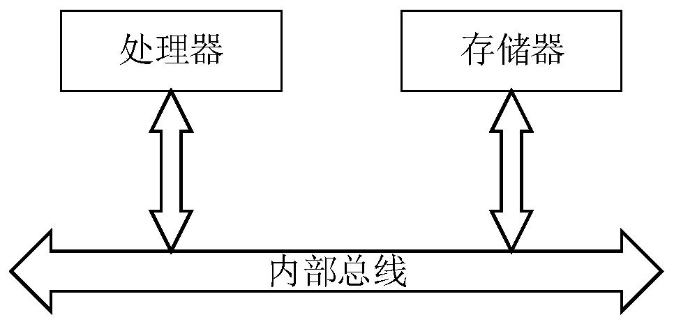
[0033] The equipment failure alarm device of this embodiment is as follows: figure 1 As shown, the device includes a processor and a memory, and the processor executes the computer program stored in the memory to implement the equipment failure ala...

Embodiment approach 2

[0062] Embodiment 2 relates to an embodiment of an equipment failure alarm method and an embodiment of an equipment failure alarm device.

[0063] The structure of the equipment failure alarm device in this embodiment is the same as that in Embodiment 1, the difference lies in that the equipment failure alarm method that can be realized by the equipment failure alarm device in this embodiment is different from that in Embodiment 1.

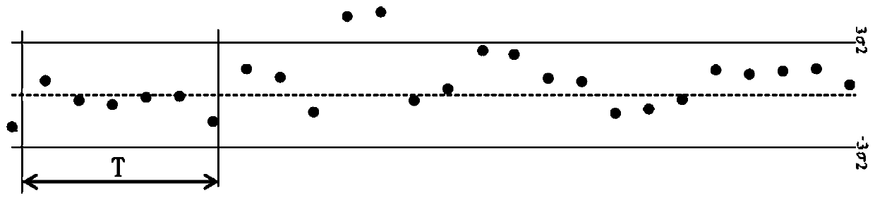
[0064] The equipment failure alarm method of this embodiment differs from Embodiment 1 only in that: when the operating condition of the equipment under test changes, the time window is also updated, and the alarm threshold is recalculated on the updated time window. For example, if the operating condition of the equipment under test changes from a stable condition to a variable speed condition, the alarm threshold is recalculated on the time window corresponding to the variable speed condition.

[0065] As shown in Table 1, the operating conditio...


PUM


Abstract

The invention provides an equipment fault alarm method and device, and belongs to the field of equipment fault alarm. The method comprises the following steps: acquiring a vibration signal of to-be-tested equipment, and calculating the statistical magnitude of the vibration signal; monitoring the operation condition of the to-be-tested equipment, and comparing the statistical magnitude of the vibration signal with an alarm threshold corresponding to the current operation condition if the operation condition is not changed; if the operation condition changes, recalculating an alarm threshold value, comparing the statistical magnitude of the vibration signal with the alarm threshold value corresponding to the changed operation condition, and determining whether to generate an alarm signal ornot according to a comparison result, wherein the alarm threshold value corresponds to the operation condition of the to-be-tested equipment, calculating the statistical magnitude of the vibration signals of the to-be-tested equipment in a time window under a certain operation condition, and determining the alarm threshold value of the operation condition according to the statistical magnitude ofthe vibration signals of the to-be-tested equipment in the time window. The method can adapt to various operation working conditions, and the fault alarm accuracy of equipment with complex working conditions is improved.

Description

technical field [0001] The invention relates to an equipment failure alarm method and device, and belongs to the technical field of equipment failure alarm. Background technique [0002] Bearings and gears are the most used parts of rotating equipment. If they break down and are not found and eliminated in time, it will cause the equipment to aggravate the vibration, and in severe cases, it will cause equipment damage. Therefore, it is particularly important to carry out fault alarm and fault diagnosis for bearings or gears. Among them, the fault alarm refers to sending out an alarm signal when the change of the collected equipment vibration signal meets the set alarm rules. For example, when the amplitude of the equipment vibration signal exceeds the set alarm threshold, an alarm signal is sent for fault alarm. It means to further determine whether the equipment is actually faulty after receiving the alarm signal and to accurately judge the type of equipment failure when t...

Claims


Application Information

Patent Timeline
IPC IPC(8): G01H17/00G01M13/028G01M13/021G01M13/045G08B21/18
CPCG01H17/00G01M13/028G01M13/021G01M13/045G08B21/182G08B21/187
Inventor 李永耀雷文平韩捷陈磊胡鑫王宏超李凌均王丽雅
Owner 郑州恩普特科技股份有限公司
Why Eureka
Try Eureka