Test equipment for automated quality control of thin film solar modules

a technology of solar modules and test equipment, applied in printed circuit testing, photovoltaic monitoring, instruments, etc., can solve the problems of high cost, size and durability, single-crystal silicon ingot production, and significant drawbacks of crystalline silicon pv cells

Inactive Publication Date: 2008-10-23
OERLIKON SOLAR AG (TRUEBBACH)
View PDF5 Cites 68 Cited by
  • Summary
  • Abstract
  • Description
  • Claims
  • Application Information

AI Technical Summary

Benefits of technology

[0011]According to one aspect, the present invention provides a test system for identifying a defective region of a photovoltaic cell from among a plurality of photovoltaic cells collectively forming a thin film solar module. The test system includes a probe comprising a plurality of test fingers that are arranged to each be substantially simultaneously placed adjacent to an electric contact provided to different regions of one or more of the plurality of photovoltaic cells. Each of the test fingers is to receive an electrical output from the different regions of the one or more photovoltaic cells. The test system further includes a light source that emits light to be converted by the photovoltaic cells into the electrical output during testing, and a measurement circuit that measures a property of the electrical output received from the different regions of the photovoltaic cells and transmits a measured value signal indicative of the property measured by the measurement circuit. A control unit is operatively coupled to the measurement circuit for receiving the measured value signal and generating a visible display indicating that at least one of the different regions of the solar module is a defective region based at least in part on the measured value signal and indicating a location of the defective region on the solar module.

Problems solved by technology

But crystalline silicon PV cells have significant drawbacks, the most notable of which include cost, size and durability.
The single-crystal silicon ingot is produced by a lengthy, costly and heat-and-pressure-sensitive process.
This creates a significant demand for a limited supply of wafers formed from single-crystal silicon, and in turn, high costs associated with such wafers.
The process of producing single-crystal silicon wafers also limits the maximum diameter of the wafers on which individual PV cells are to be formed.
However, the longer the single-crystal silicon is permitted to grow the more likely it is that imperfections will be introduced into the silicon crystal lattice from conditions such as temperature and / or pressure fluctuations, the speed at which the ingot is drawn from the melt, impurities in the melt.
Due to the cost considerations mentioned above this will often make crystalline silicon PV cells economically impractical for commercial applications.
Further, crystalline silicon PV cells are typically fragile and sensitive to environmental conditions such as moisture.
This requires sealing the PV cells of an array within a rugged enclosure, adding additional costs to such arrays of crystalline PV cells.
Although thin film PV cells include more cost effective and readily-available materials, they do not produce as much electric energy as crystalline silicon PV cells, on average.
When such an array of thin film PV cells does not perform as expected it is often the result of an imperfection in one or more of the individual thin film PV cells.
But due to the large number of such cells in the array, however, locating the offending cells is a daunting and time-consuming task.

Method used


Image

  • Test equipment for automated quality control of thin film solar modules
  • Test equipment for automated quality control of thin film solar modules
  • Test equipment for automated quality control of thin film solar modules

Examples


Embodiment Construction

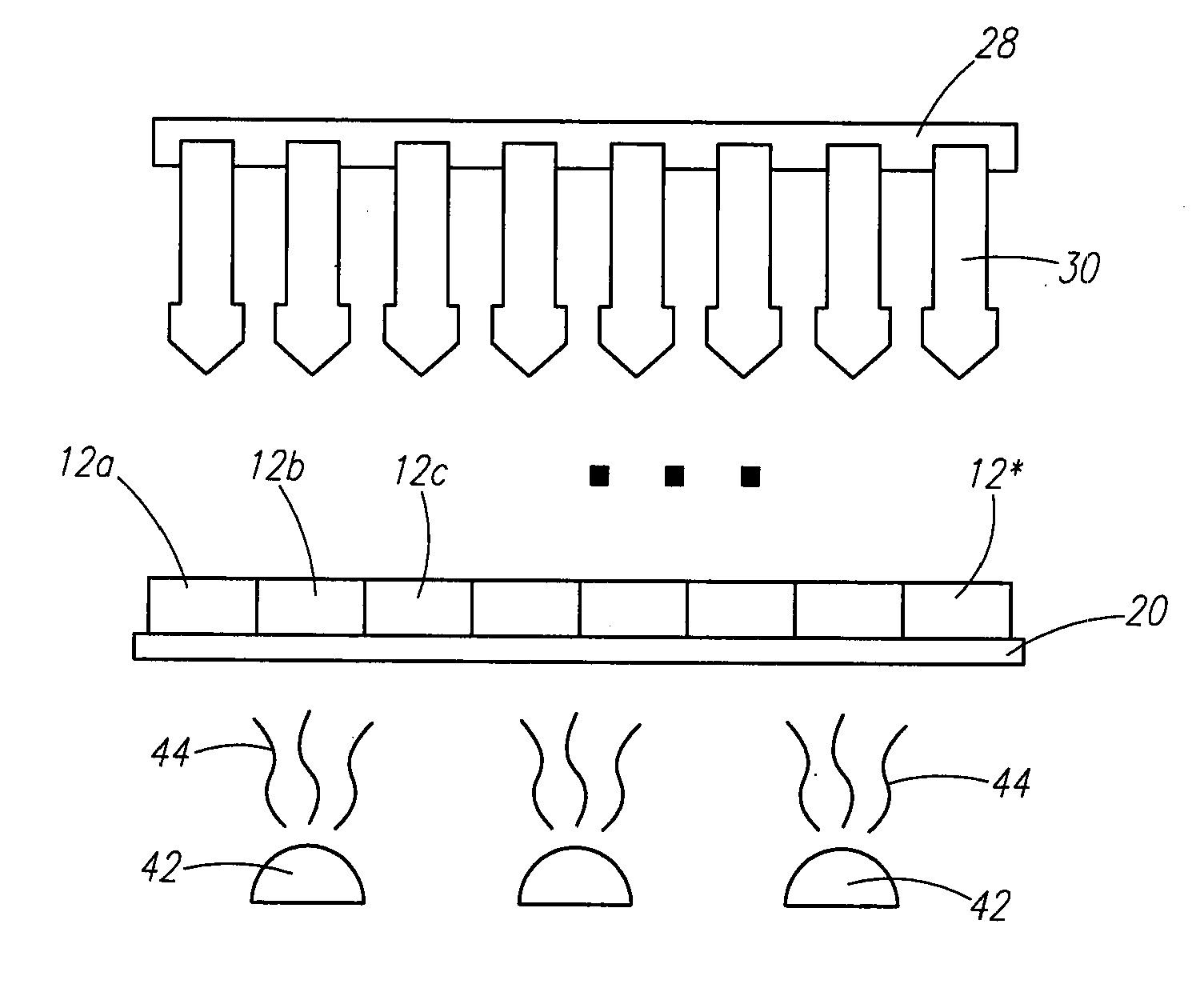
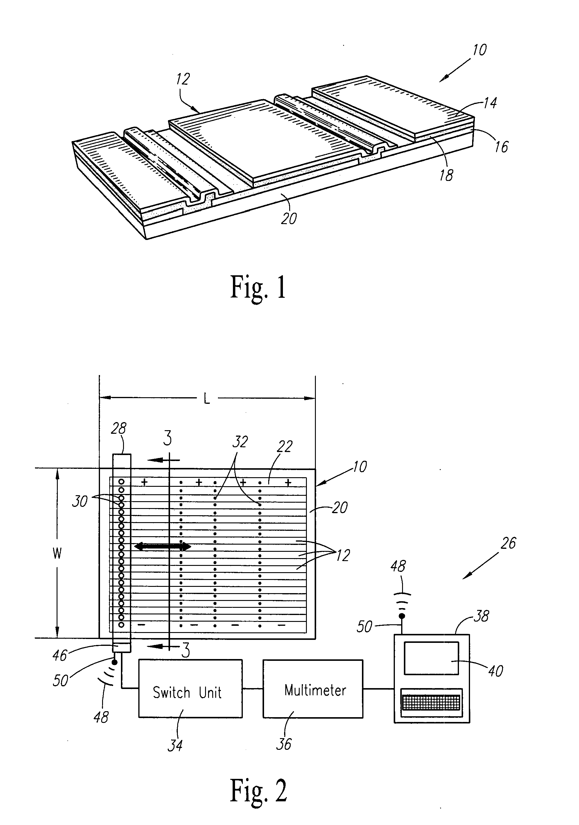
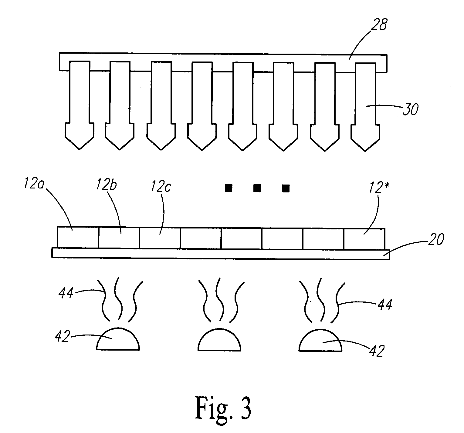
[0021]Certain terminology is used herein for convenience only and is not to be taken as a limitation on the present invention. Relative language used herein is best understood with reference to the drawings, in which like numerals are used to identify like or similar items. Further, in the drawings, certain features may be shown in somewhat schematic form.

[0022]It is also to be noted that the phrase “at least one of”, if used herein, followed by a plurality of members herein means one of the members, or a combination of more than one of the members. For example, the phrase “at least one of a first widget and a second widget” means in the present application: the first widget, the second widget, or the first widget and the second widget. Likewise, “at least one of a first widget, a second widget and a third widget” means in the present application: the first widget, the second widget, the third widget, the first widget and the second widget, the first widget and the third widget, the...


PUM

PropertyMeasurementUnit
thickaaaaaaaaaa
surface areasaaaaaaaaaa

Abstract

Provided is a method and test system for identifying a defective region of a photovoltaic cell from among a plurality of photovoltaic cells collectively forming a thin film solar module. A probe includes a plurality of test fingers arranged to be substantially simultaneously placed adjacent to an electric contact provided to different regions of one or more of the plurality of photovoltaic cells, and each of the test fingers is to receive an electrical output from the different regions of the one or more photovoltaic cells. A light source emits light to be converted by the photovoltaic cells into the electrical output during testing. A measurement circuit measures a property of the electrical output received from the different regions of the photovoltaic cells and transmits a measured value signal indicative of the property measured by the measurement circuit. And a control unit receives the measured value signal and generates a visible display indicating that at least one of the different regions of the solar module is a defective region based at least in part on the measured value signal, and also indicates a location of the defective region on the solar module.

Description

BACKGROUND OF THE INVENTION[0001]1. Field of the Invention[0002]The present invention is directed generally toward the testing of thin film solar modules to detect malfunctions and, more specifically, toward a method and apparatus for testing a plurality of individual photovoltaic cells electrically coupled together in series to localize any of the individually tested photovoltaic cells that are not performing as desired.[0003]2. Description of Related Art[0004]Traditionally, photovoltaic (“PV”) cells referred to as crystalline silicon PV cells included a substrate formed from crystalline silicon to act as the light-absorbing semiconductor. Light energy from the sun is absorbed within the silicon and converted into electric energy. Single-crystal silicon wafers sliced from an ingot of single-crystal silicon are most often used because they offer favorable conversion efficiencies, and thus produce a desirable output of electrical energy.[0005]But crystalline silicon PV cells have sig...

Claims


Application Information

Patent Timeline
Patent Type & Authority Applications(United States)
IPC IPC(8): G01R31/02
CPCH02S50/10G01R31/2808Y02E10/50
Inventor KLUTH, OLIVERSPRINGER, JIRIMOHR, MICHAELHUGLI, ANDREAS
Owner OERLIKON SOLAR AG (TRUEBBACH)
Why Eureka
Try Eureka