Automatic telephone line switch

a telephone line switch and automatic technology, applied in the field of telecommunication switch, can solve the problems of telecommunication switch, voiding any benefits for consumers, and leaving the lec with an unused facility that still needs maintenance,

Inactive Publication Date: 2005-06-02
ARPIN CLAUDE
View PDF23 Cites 69 Cited by
  • Summary
  • Abstract
  • Description
  • Claims
  • Application Information

AI Technical Summary

Problems solved by technology

This new configuration creates a problem involving an expensive service call by maintenance personnel that wipes out any benefits to consumers afforded by competition in the local telephone industry.
On the other hand, a CAP completely removes the subscriber and the revenue stream, leaving the LEC with an unused facility that still requires maintenance.
A telecommunications switch as described by Nolde, U.S. Pat. No. 5,920,615, dated Jul. 6, 1999 is also not feasible to eliminate service calls because it is designed to switch a plurality of normal communication apparatus on a single local telephone line using four wires.
In addition a Nolde-type master-slave system does not solve the equal access issues.
Powering equipment to switch telephone lines at the Demarcation Points 34 and 34A is also a serious problem not envisioned by any prior equipment.
The Meeske equipment also adds tremendous complexity to the network.
Errors of one company in programming such equipment could result in loss of service to a competitor's subscriber.
While using local AC power is not an option, using the telephone line power to operate equipment at the demarcation points 34 and 34A poses serious problems because that power is intended to operate customer-premises equipment such as telephones, fax machines, modems and CallerID devices that rely on the power available from the local telephone line such as described by Ninh, U.S. Pat. No. 6,212,274 B1, dated Apr. 3, 2001.
The problem is compounded by maintenance equipment used by the service providers such as equipment described by Liu, U.S. Pat. No. 6,266,395 B1, dated Jul. 24, 2001.

Method used


Image

  • Automatic telephone line switch
  • Automatic telephone line switch
  • Automatic telephone line switch

Examples


Embodiment Construction

ATLS Network Connection

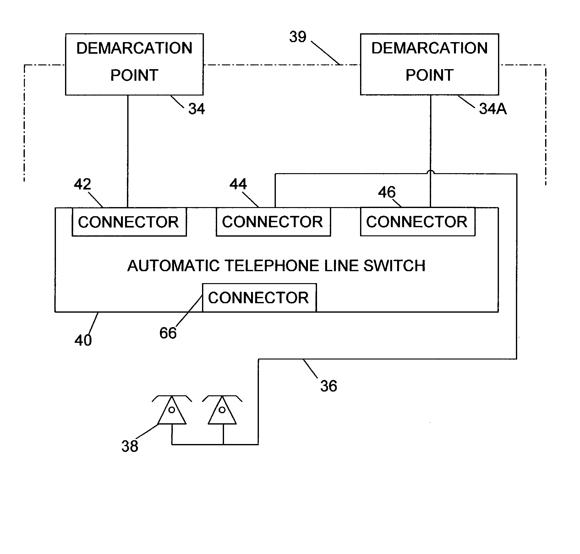
[0025] The connections between the ATLS 40, the local networks and the customer-premises telephone line are shows in FIG. 4. The customer-premises telephone line is connected to connector 44 while the LEC network is connected to 42 and the CAP network is connected to 46. Connector 66 is used to program the central processor 162.

Detailed Block Diagram

[0026] A more detailed block diagram of one embodiment of the ATLS is shown in FIG. 5. The latching relay 58 has two coils 48 and 48A. The side B line interface 62 activated coil 48 to force relay 58 to toggle and establish a connection between connector 42 and 44. Conversely the Side A line interface 62A activated coil 48A to force relay 58 to toggle and establish the connection between connector 44 and 46. Protection 50 is a combination of an over-voltage and current limiting circuit to protect relay 58 from transient that may be present on the telephone line at 42. This protection is designed to pass, without...


PUM


Abstract

An apparatus (40) and method for switching a customer-premises telephone line (36) between a plurality of local telephone networks (35). The local telephone networks may have different electrical and operational characteristics. Using less than 100 micro-amperes of current from the telephone networks, the apparatus (40) requires no external power and performs its tasks without interfering with the normal operation of the telephone networks including test equipment, terminal equipment, data transmission on the telephone line and test equipment. The method involves monitoring electrical signals on both local telephone networks (35) and using this information to assign a weight to each network. The customer-premises telephone line (36) is switched to the telephone network having the highest weight. The advantages are the elimination of a service call by a technician to manually switch the customer premises telephone line (36), equal access by both service providers to the switch and a seamless interface to the telephone networks.

Description

CROSS-REFERENCE TO RELATED APPLICATIONS [0001] The present application clams priority from U.S. Provisional application Ser. No. 60 / 350,981, filed Jan. 25, 2002, which is incorporated herein by reference.FIELD OF THE INVENTION [0002] This Automatic telephone Line Switch (ATLS) relates to a telecommunication switch designed to switch a customer-premises two-wire telephone line between one of a plurality of local telephone networks owned by independent telephone service providers. The switching is performed at the subscriber's end of the network without the intervention of an on-site service technician. BACKGROUND OF INVENTION [0003] Traditionally most local telephone networks belonged to the same telephone company. This company was broken up into several Regional Bell Operating Companies (RBOC). These telephone service providers are now called Local Exchange Carriers (LEC). Every subscriber that has local (i.e.: not long distance, not cellular) telephone service is connected to a loc...

Claims


Application Information

Patent Timeline
Patent Type & Authority Applications(United States)
IPC IPC(8): H04M1/24H04M1/738H04M3/00H04M3/08H04M3/22H04M3/30H04M3/42H04M7/00H04Q3/00
CPCH04M1/738H04M3/005H04M3/2245H04M3/30H04Q2213/1338H04Q3/0016H04Q2213/13109H04Q2213/13149H04M3/42289
Inventor ARPIN, CLAUDE
Owner ARPIN CLAUDE
Why Eureka
Try Eureka