

High speed serial interface test
a serial interface and high-speed technology, applied in the field of serial communication devices, can solve the problems of difficult for test equipment to effectively test a serial communication device, problems for testing engineers, etc., and achieve the effect of high-speed testing of complex serial interfaces
- Summary
- Abstract
- Description
- Claims
- Application Information
AI Technical Summary
Benefits of technology
Problems solved by technology
Method used
Image

Examples
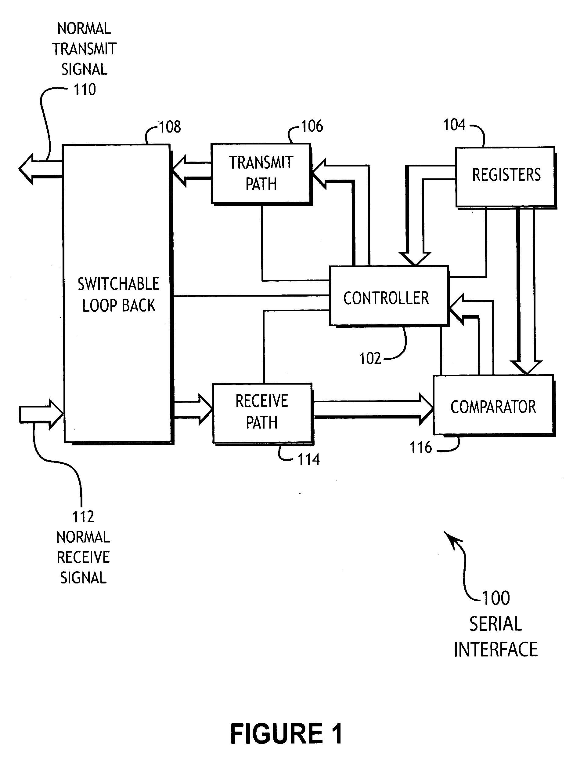
embodiment 100
[0015]FIG. 1 illustrates an embodiment 100 of the present invention showing a serial interface with a built-in self-test apparatus. A controller 102 communicates with a set of registers 104 to retrieve a word or set of words. The controller 102 may send those words repeatedly through a transmit path 106, a switchable loopback path 108, and a receive path 114 to a comparator 116. The comparator 116 may compare the received series of words with the initial words found in the registers 104.
[0016]The embodiment 100 enables a repeated set of words to exercise all of the transmit and receive portions of the interface at the highest speed possible because no external test equipment is required. Typically, the exercising of an interface may require a long string of data that is supplied at one end of the interface and transmitted through the interface. The present invention only uses a series of repeated words that are stored in the register 104, thus severely eliminating the amount of data...
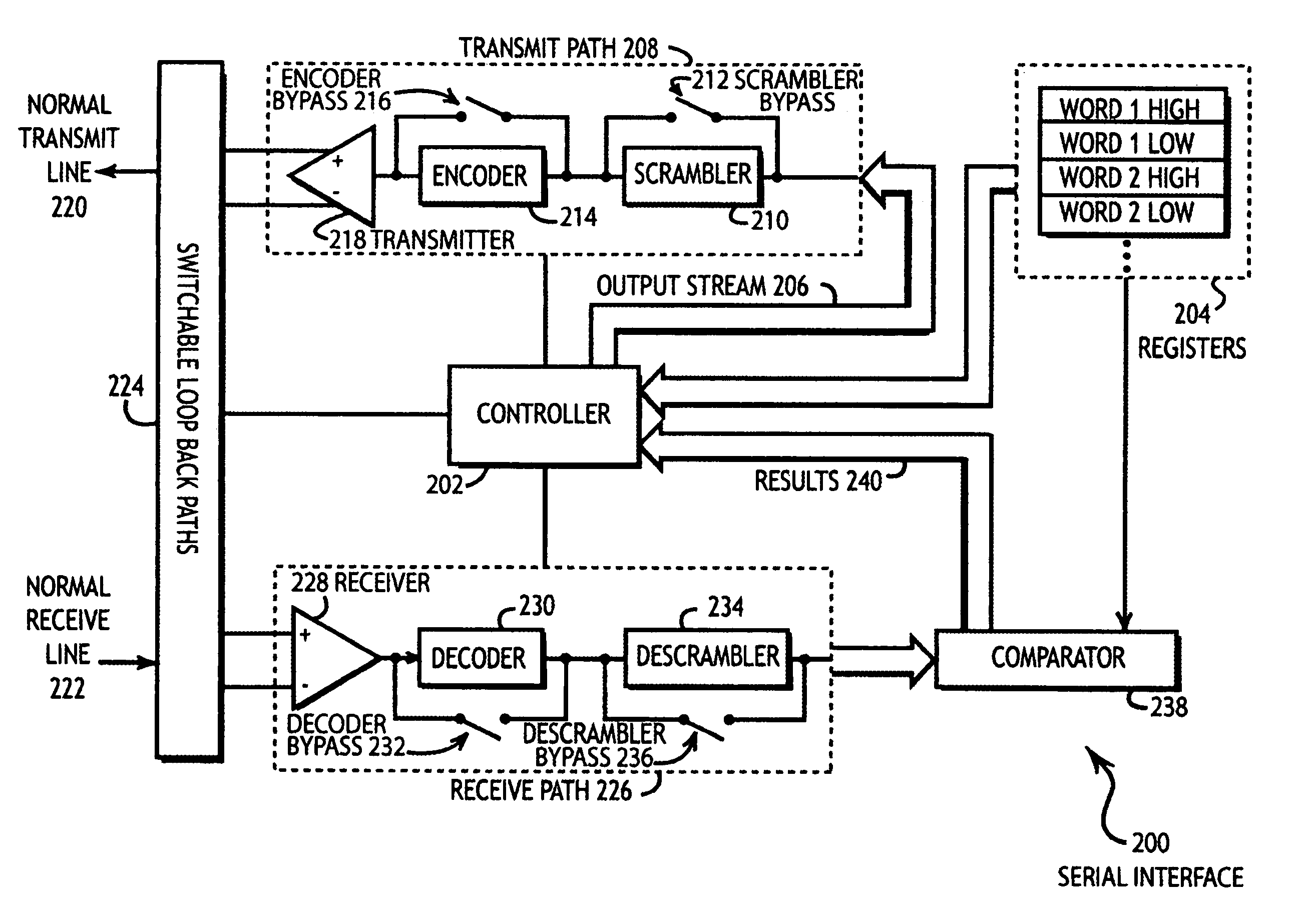
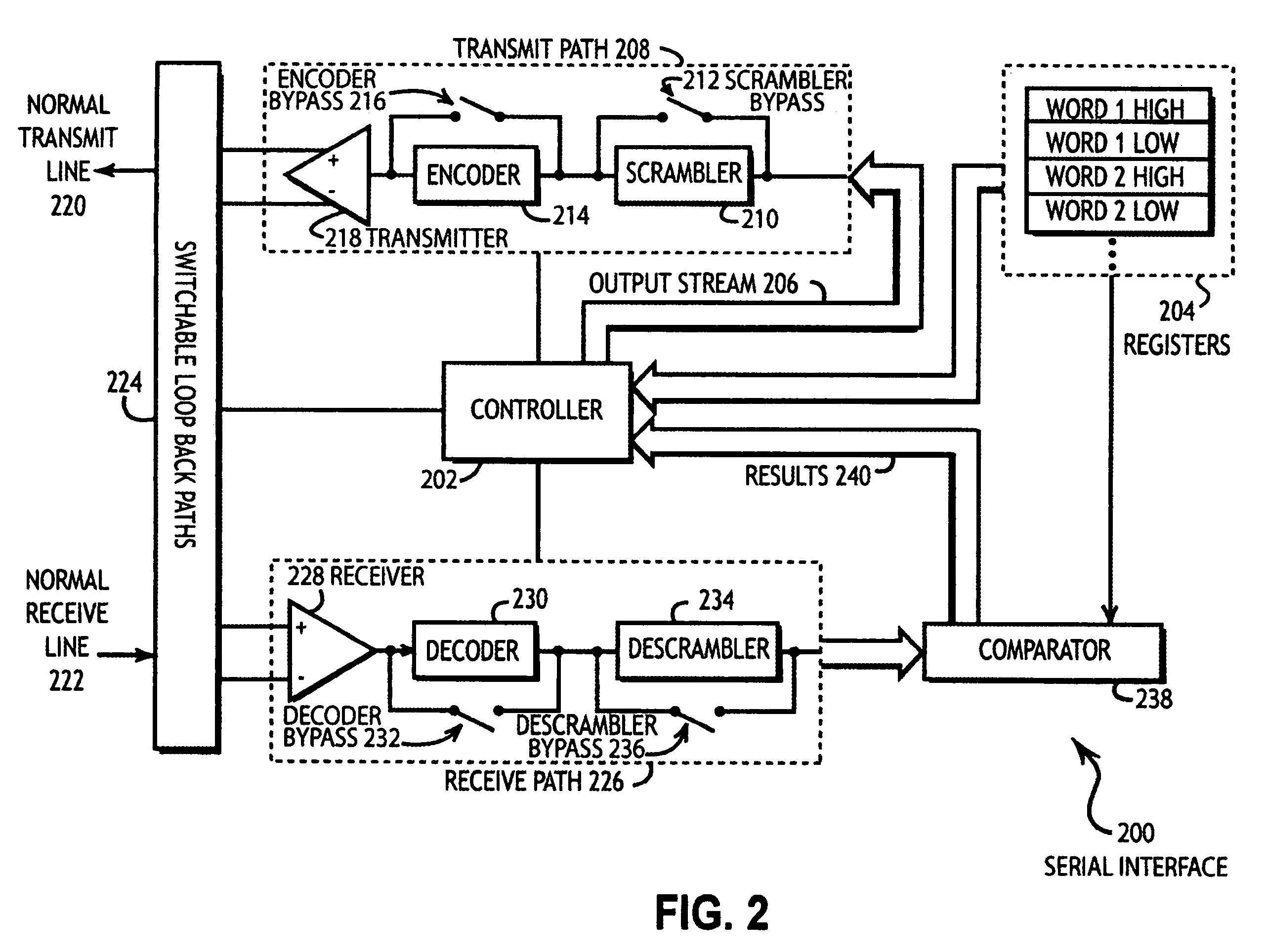
embodiment 200
[0019]The embodiment 200 may use the function of the scrambler 210 and descrambler 234 to create a pseudo-random sequence of data that may be sent out the transmit path 208 and received by the receive path 226 at the full speed of the interface 200. In this manner, each component that may be necessary to transmit and receive data may be fully exercised and thereby tested. Various bypass switches 212, 216, 232, and 236 allow some functionality to be switched in and out of the device to aid troubleshooting.
[0020]In some embodiments, the circuitry for the serial interface 200 may be constructed on a single integrated circuit chip. In such an embodiment, the switched loopback paths 224 may be switchable circuits within the chip that allow the chip to perform a self test without any external signal paths. In other embodiments, the switched loopback paths 224 may be an external loopback that is mechanically attached to a device such as a computer or peripheral device for the purposes of p...
embodiment 300
[0026]FIG. 3 illustrates an embodiment 300 of the present invention showing a method for testing a serial interface. The process begins in block 302. A primitive is sent between the scrambler and descrambler to synchronize those elements in block 304. Words are read from the register and a repeating stream is created in block 306. The stream is scrambled in block 308 and encoded in block 310 before being transmitted in block 312 and received in block 314. The received stream is decoded in block 316 and descrambled in block 318. The descrambled output stream is compared to the repeated input words in block 320. If an error occurred in block 322, the error is counted in block 324 and the process repeats in block 306.
[0027]The embodiment 300 illustrates a method wherein a pseudo-random testing sequence may be generated by using only one or more words stored in a register. The words are used to create a scrambled and encoded output that is pseudo-random and may thereby more fully exerci...
PUM
 Abstract
Description
Claims
Application Information