Supercharge Your Innovation With Domain-Expert AI Agents!

Synchronous phase modifier rotor current protection method and system

A technology of rotor current and protection system, applied in emergency protection circuit devices, emergency protection devices with automatic disconnection, electrical components, etc., can solve the problems of excitation end breakdown, insufficient timeliness, accuracy and safety

Active Publication Date: 2020-08-07
ELECTRIC POWER RESEARCH INSTITUTE OF STATE GRID SHANDONG ELECTRIC POWER COMPANY +1
View PDF8 Cites 0 Cited by
  • Summary
  • Abstract
  • Description
  • Claims
  • Application Information

AI Technical Summary

Problems solved by technology

[0006] This application provides a synchronous condenser rotor current protection method and system to solve the problem that the timeliness, accuracy and safety of the synchronous condenser rotor overcurrent protection in the prior art are not high enough, and there are repeated excitations in the case of strong excitation. The problem of being broken down

Method used


Image

  • Synchronous phase modifier rotor current protection method and system
  • Synchronous phase modifier rotor current protection method and system
  • Synchronous phase modifier rotor current protection method and system

Examples


Embodiment 1

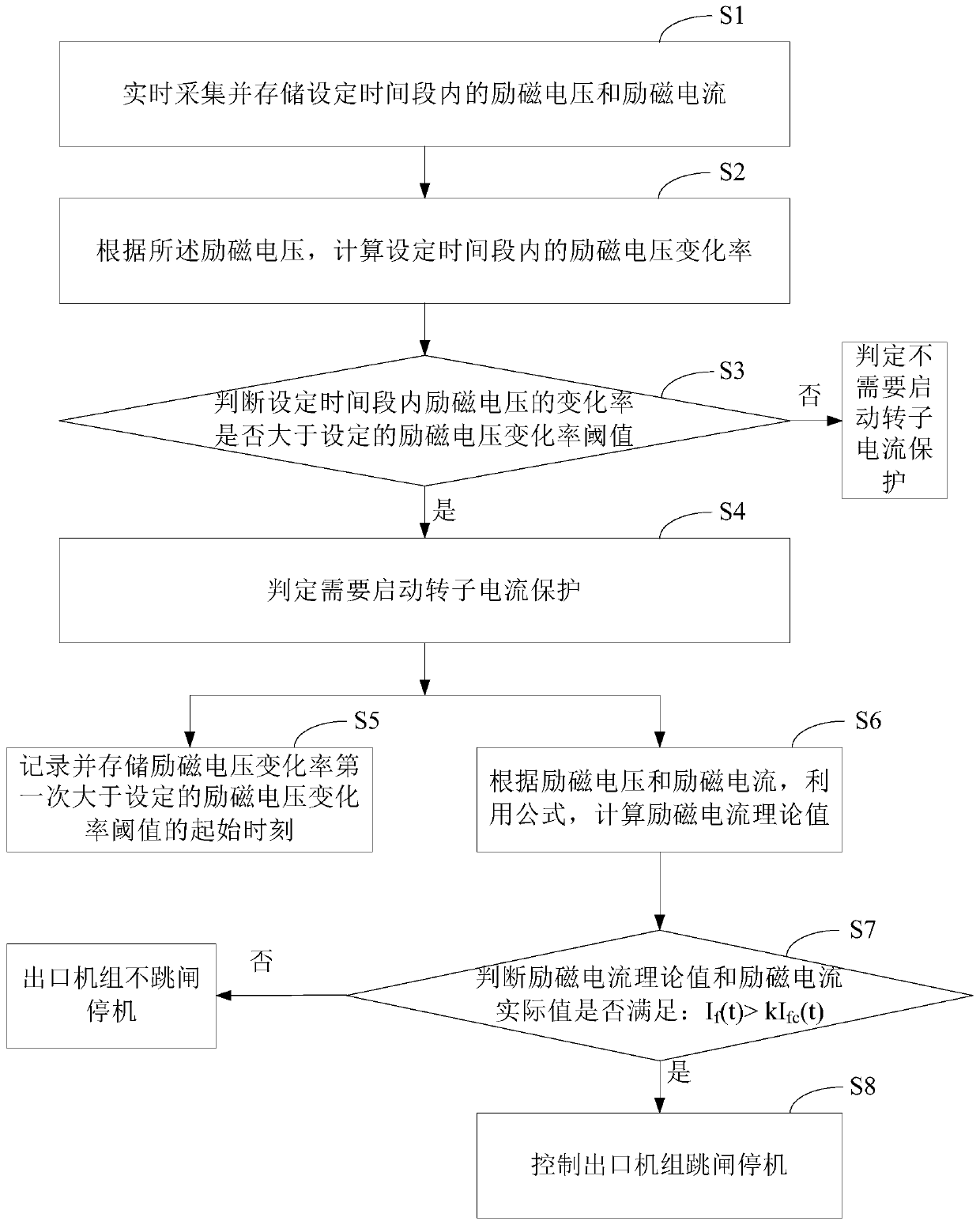
[0054] see figure 2 , figure 2 It is a schematic flowchart of a method for protecting a rotor current of a synchronous condenser provided in an embodiment of the present application. Depend on figure 2 It can be seen that the rotor current protection method of the synchronous condenser in this embodiment mainly includes the following process:

[0055] S1: Collect and store the excitation voltage and excitation current within the set time period in real time.

[0056] Specifically, step S1 includes the following processes:

[0057] S11: Collect the excitation voltage and excitation current within the set time period.

[0058] In this embodiment, the method of collecting the excitation voltage and the excitation current is to set a time period and collect in real time. That is: within a certain set time period, the excitation voltage and excitation current are collected in real time respectively.

[0059] S12: Roll and store the collected excitation voltage and excitati...

Embodiment 2

[0102] exist Figure 2-Figure 5 On the basis of the illustrated embodiment see Figure 6 , Figure 6 It is a schematic structural diagram of a rotor current protection system for a synchronous condenser provided in an embodiment of the present application. Depend on Figure 6 It can be seen that the rotor current protection system of the synchronous condenser in this embodiment mainly includes: an acquisition module, a first calculation module, a first judgment module, a recording module, a second calculation module, a second judgment module and a control module.

[0103] Wherein, the collection module is used for real-time collection and storage of excitation voltage and excitation current within a set period of time. The first calculation module is used to calculate the rate of change of the excitation voltage within a set time period according to the excitation voltage. The first judging module is used for judging whether the rate of change of the excitation voltage is ...


PUM


Abstract

The invention discloses a synchronous phase modifier rotor current protection method and system. The method comprises the steps of collecting and storing excitation voltage and excitation current in aset time period; judging whether the change rate of the excitation voltage in the set time period is greater than a set threshold value of the change rate of the excitation voltage; if so, judging that rotor current protection needs to be started; recording and storing a starting moment when the excitation voltage change rate is greater than a set excitation voltage change rate threshold value for the first time; calculating an exciting current theoretical value by utilizing a formula according to the exciting voltage and the exciting current; judging whether the excitation current theoretical value and the excitation current actual value meet the condition that If(t) is larger than kIfc (t) or not; and if so, controlling an outlet unit to trip and stop. The system comprises an acquisition module, a first judgment module, a first calculation module, a recording module, a second calculation module, a second judgment module and a control module. According to the invention, the timeliness and accuracy of rotor overcurrent protection in response to rotor overcurrent faults caused by excitation end breakdown can be effectively improved.

Description

technical field [0001] The present application relates to the technical field of electric power system relay protection, in particular to a synchronous condenser rotor current protection method and system. Background technique [0002] Compared with conventional generator sets, condensers positioned to provide subtransient and transient reactive power support usually have higher excitation capabilities. Accompanied by a high strong excitation capability, there is a risk of instantaneous breakdown of the positive and negative poles of the excitation terminal when the excitation voltage is too high when the condenser is strongly excited. Therefore, how to protect the rotor overcurrent caused by the breakdown of the excitation terminal of the synchronous condenser, so as to avoid the risk of repeated breakdown that may be caused by strong excitation, is an important technical problem. [0003] The function of protecting the rotor current in the prior art mainly includes excita...

Claims


Application Information

Patent Timeline
Patent Type & Authority Applications(China)
IPC IPC(8): H02H7/06H02H3/00
CPCH02H7/06H02H3/006
Inventor 朱应峰解笑苏高嵩颜庆李明张维超袁训奎孟祥荣
Owner ELECTRIC POWER RESEARCH INSTITUTE OF STATE GRID SHANDONG ELECTRIC POWER COMPANY
Features
  • R&D
  • Intellectual Property
  • Life Sciences
  • Materials
  • Tech Scout
  • Unparalleled Data Quality
  • Higher Quality Content
  • 60% Fewer Hallucinations
Learn More