Fastener

A buckle and female buckle technology, which is applied to buckles, fasteners, clothing, etc., can solve the problems of increased accidental lock release, large buttons, and inconvenient lock release operation, so as to achieve convenient lock release operation, imperceptible and safe operation Effect

Active Publication Date: 2020-08-11
WONDERLAND SWITZERLAND AG
View PDF9 Cites 6 Cited by
  • Summary
  • Abstract
  • Description
  • Claims
  • Application Information

AI Technical Summary

Problems solved by technology

[0004] At present, for the traditional buckle, it includes a male buckle, a female buckle and a button. The male buckle and the female buckle are fastened and fixed to each other. The front of the buckle is either located at the back of the male buckle or the female buckle, so that the button is in a very conspicuous position, so that people can quickly find the button, so as to facilitate the pressing operation of the button; however, because the button is in a very conspicuous position Therefore, it is very easy for infants riding in the infant carrier to find the button and touch it subconsciously, thus increasing the risk of accidental release
At the same time, the traditional buckle requires a large force to act on the button when releasing the lock, which increases the difficulty of the unlocking operation
Secondly, the position of the button is set on the front and back surfaces of the male buckle or the female buckle, which increases the chance of scratching with external objects, thereby increasing the risk of accidental release of the lock; of course, there are also buckles with strong concealed buttons on the market, but The structure of the buckle is complicated, and it is inconvenient to release the lock

Method used


Image

  • Fastener
  • Fastener
  • Fastener

Examples


Embodiment Construction

[0042] In order to describe the technical content and structural features of the present invention in detail, further description will be given below in conjunction with the implementation and accompanying drawings.

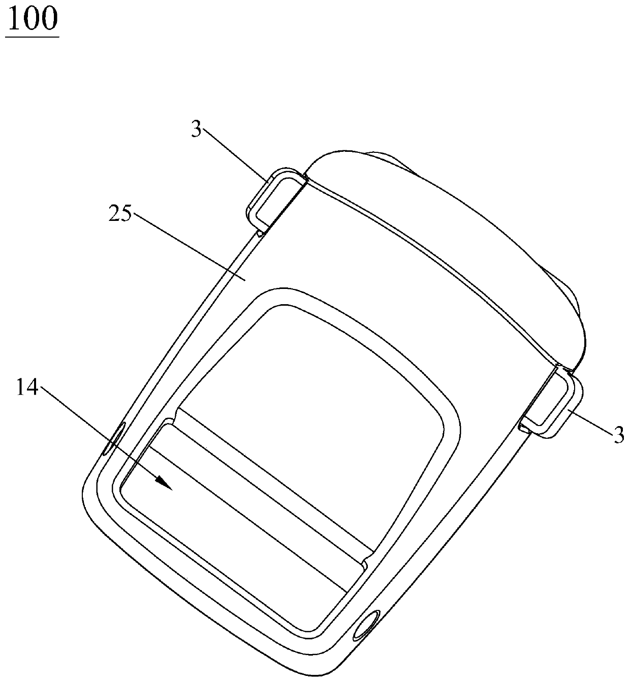
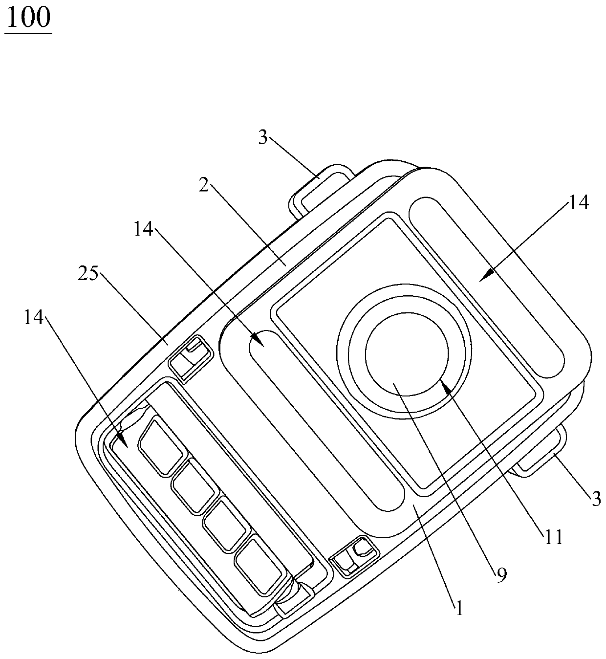
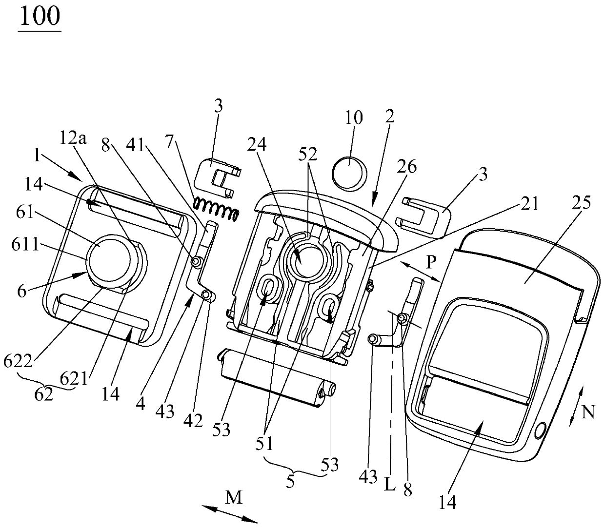
[0043] see Figure 1 to Figure 4 , the buckle 100 of the present invention includes a male buckle 1 , a female buckle 2 , a release operation member 3 and a lever 4 . The female buckle 2 has a locking portion 5, and the male buckle 1 has a mating lock portion 6 for cooperating with the locking portion 5; the male buckle 1 and the female buckle 2 are mated along a direction close to each other (such as image 3The direction indicated by the middle arrow P) to make the locking part 5 lock with the mating lock part 6; of course, in other embodiments, the male buckle 1 can have the locking part 5, and correspondingly, the female buckle 2 can have the locking part 5 for matching with The mating locking part 6 mated with the locking part 5 can also realize the locking...


PUM


Abstract

The invention discloses a fastener, which comprises a male fastener, a female fastener, an unlocking operation piece and a lever pivoted on the male fastener or the female fastener around a pivoting center line, one of the male fastener and the female fastener is provided with a locking part, and the other one of the male fastener and the female fastener is provided with a plug-in matching lockingpart matching the locking part; the male buckle and the female buckle are oppositely inserted in the direction close to each other so that the locking part and the oppositely-inserted lock matching part can be locked. The unlocking operation part is movably arranged on the side wall of the male fastener or the female fastener where the lever is located; the pivoting center line is located betweenthe first end and the second end of the lever, the unlocking operation piece is connected with the first end of the lever, the second end of the lever and the locking part are arranged in a linkage mode, the lever is driven by the unlocking operation piece to rotate around the pivoting center line, and the rotating lever is in linkage with the locking part to be disengaged from locking of the plug-in matching lock part. The fastener has the advantages of being convenient to unlock and operate and simple in structure on the basis of guaranteeing high concealment of the unlocking operation piece.

Description

technical field [0001] The invention relates to the field of infant carriers, in particular to a buckle. Background technique [0002] With the continuous development of the economy and the continuous progress of science and technology, extremely rich material consumer goods are provided for people's lives, and infant vehicles are one of many material consumer goods. [0003] As we all know, the use of braided straps is indispensable in infant carriers; in order to allow different braided straps to be assembled and disassembled at any time, the use of buckles is indispensable. [0004] At present, for the traditional buckle, it includes a male buckle, a female buckle and a button. The male buckle and the female buckle are fastened and fixed to each other. The front of the buckle is either located at the back of the male buckle or the female buckle, so that the button is in a very conspicuous position, so that people can quickly find the button, so as to facilitate the press...

Claims


Application Information

Patent Timeline
Patent Type & Authority Applications(China)
IPC IPC(8): A44B11/25
CPCA44B11/2526
Inventor 程满群
Owner WONDERLAND SWITZERLAND AG
Why Eureka
Try Eureka