Automatic punching die device

An automatic punching and mold technology, applied in the field of punching processing, can solve the problems of low efficiency and low precision, and achieve the effect of high precision and high efficiency

Pending Publication Date: 2020-08-11
肇庆市高要区伟顺机械设备有限公司
View PDF0 Cites 0 Cited by
  • Summary
  • Abstract
  • Description
  • Claims
  • Application Information

AI Technical Summary

Problems solved by technology

[0002] After the flange is initially formed, it needs to be followed by drilling. Since punching is more efficient than drilling, many people use punching machines to punch flanges. Generally, manual marking is required for punching. To process the position of the hole, it is necessary to manually align the stamping head with the workpiece, which is inefficient and has low precision.

Method used


Image

  • Automatic punching die device
  • Automatic punching die device
  • Automatic punching die device

Examples


Embodiment Construction

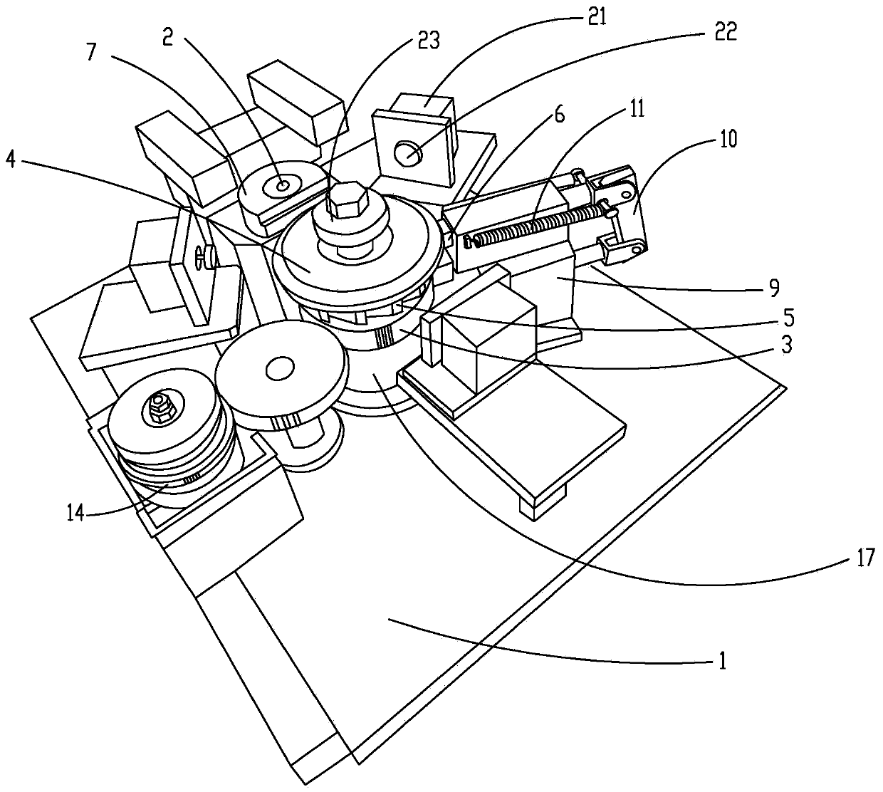
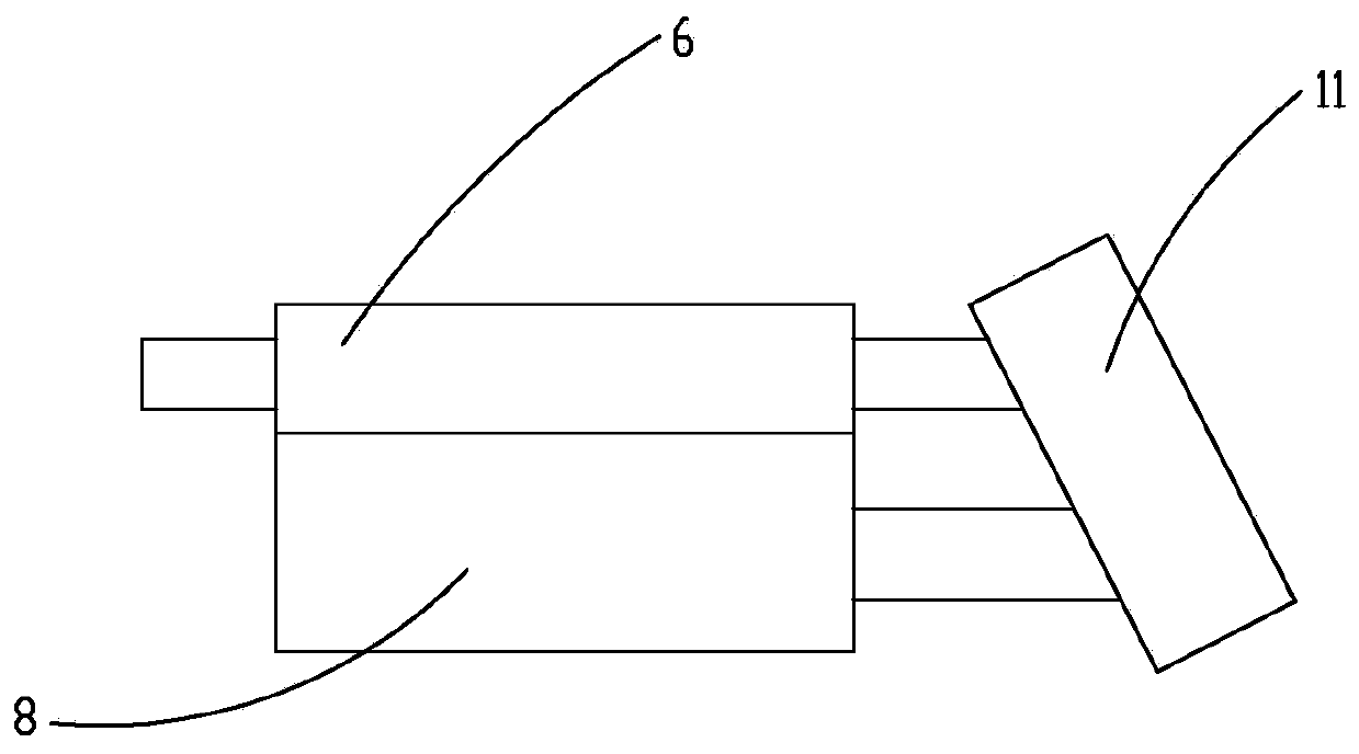
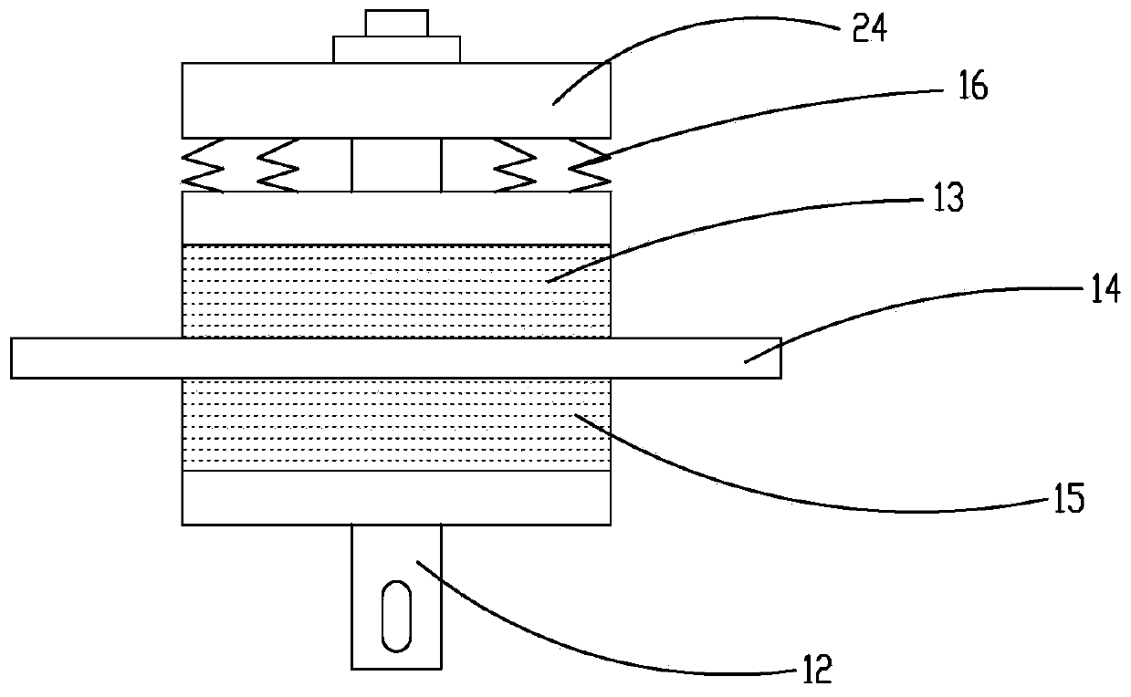
[0022] like Figure 1~5 The embodiment of the present invention shown is an automatic punching die device, including a working platform 1, the working platform 1 is provided with a motor, a rotary oil cylinder, a positioning device and a stamping column 7, and the rotary oil cylinder is provided with a transmission gear 3, and the transmission gear 3 is fixed On the cylinder body of the rotary oil cylinder, the cylinder body and the transmission gear 3 rotate together. The motor and the transmission gear 3 are connected to drive the rotary oil cylinder to rotate. The top of the rotary oil cylinder is provided with a supporting tray 4 for placing workpieces. The rotation of the supporting tray 4 drives The workpiece rotates, and the bottom of the supporting tray 4 is provided with a ratchet 5. The positioning device includes a pawl block 6 that cooperates with the ratchet 5. The pawl block 6 can move to approach or move away from the ratchet 5. When the pawl block 6 is inserted ...


PUM


Abstract

The invention discloses an automatic punching die device. The die device comprises a working platform, wherein the working platform is provided with a motor, a rotary oil cylinder, a positioning device and a stamping column, the rotary oil cylinder is provided with a transmission gear, the motor is in transmission connection with the transmission gear to drive the rotary oil cylinder to rotate, the top of the rotary oil cylinder is provided with a bearing tray for placing a workpiece, the bottom of the bearing tray is provided with a ratchet wheel, the positioning device comprises a pawl blockmatched with the ratchet wheel, and the stamping column is provided with a stamping hole matched with a stamping head. By using the die device, automatic conveying and positioning of the workpiece can be achieved, the efficiency is high, and the precision is high.

Description

technical field [0001] The invention relates to the field of punching processing, in particular to an automatic punching die device. Background technique [0002] After the flange is initially formed, it needs to be followed by drilling. Since punching is more efficient than drilling, many people use punching machines to punch flanges. Generally, manual marking is required for punching. To process the position of the hole, it is necessary to manually align the stamping head with the workpiece, which is inefficient and has low precision. Contents of the invention [0003] The technical problem to be solved by the present invention is to provide an automatic punching die device, which can realize automatic conveying and positioning of workpieces with high efficiency and high precision. [0004] Technical scheme of the present invention is: [0005] An automatic punching die device, including a working platform, the working platform is provided with a motor, a rotary oil cy...

Claims


Application Information

Patent Timeline
Patent Type & Authority Applications(China)
IPC IPC(8): B21D28/36B21D28/34B21D43/00B21D43/14
CPCB21D28/34B21D28/36B21D43/003B21D43/14
Inventor 宋卫江
Owner 肇庆市高要区伟顺机械设备有限公司
Why Eureka
Try Eureka