Composition of conveying device for machine tool production

A technology for transportation devices and machine tools, applied in metal processing equipment, metal processing, manufacturing tools, etc., can solve the problems of increased installation difficulty and different weights of parts, and achieve the effect of simple operation and convenient ascending.

Active Publication Date: 2020-08-11
青岛张氏力拓精密机械有限公司
View PDF19 Cites 1 Cited by
  • Summary
  • Abstract
  • Description
  • Claims
  • Application Information

AI Technical Summary

Problems solved by technology

[0003] The purpose of the present invention is to solve the problem that some important parts need to be installed at different heights or different positions during the production process of the machine tool in the above-mentioned background technology, and the weight of the parts is different. If the parts are lighter, the installer It is possible to hold the parts for installation at a suitable height and position, and it is convenient to adjust the angle. However, when encountering heavy parts, it is difficult for the staff to pick them up, and it is even more inconvenient to adjust the installation angle during installation. As a result, when installing heavier parts, the difficulty of installation increases, and there is a lack of a certain aspect to provide

Method used


Image

  • Composition of conveying device for machine tool production
  • Composition of conveying device for machine tool production
  • Composition of conveying device for machine tool production

Examples


Embodiment Construction

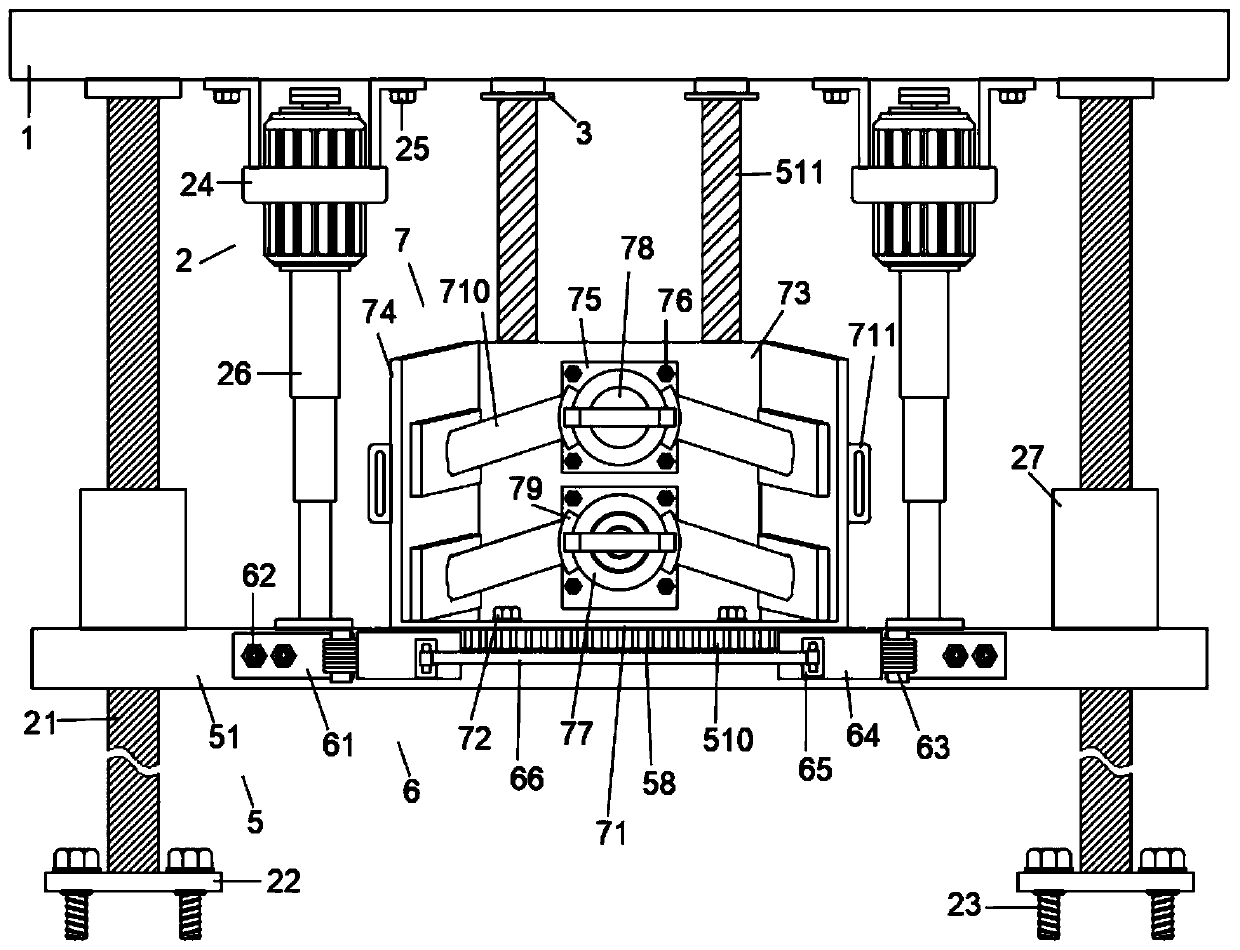
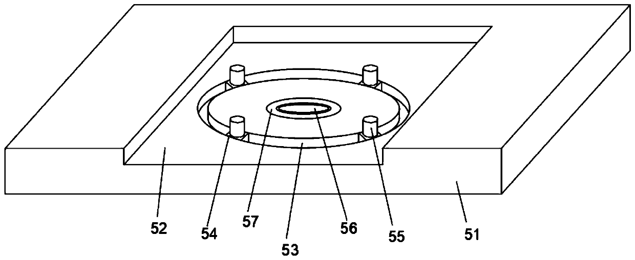
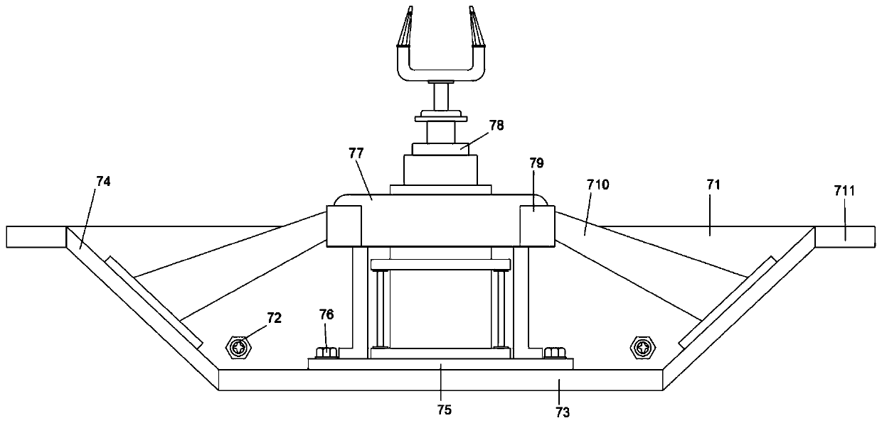
[0032] Such as Figure 1-9 As shown, this specific embodiment adopts the following technical solutions: a transportation device for machine tool production, including a top plate 1, the bottom four corners of the top plate 1 are respectively connected with the top four corners of the lifting mechanism 2, and the top plate 1 is located at the top of the lifting mechanism 2 An auxiliary chute 3 is excavated between them, and two other auxiliary sliders 4 are slidably connected in the auxiliary chute 3, and the ends of the two auxiliary sliders 4 away from the top plate 1 are connected with the rotating mechanism 5, and the rotating mechanism The top of the 5 is connected with a clamping and limiting mechanism 7, and both ends of the front side wall of the rotating mechanism 5 are connected with an adjusting mechanism 6;

[0033] The lifting mechanism 2 includes four supporting columns 21, a bottom plate 22, a No. 1 bolt 23, two No. 1 frames 24, a No. 2 bolt 25, an electric teles...


PUM


Abstract

The invention discloses a composition of a conveying device for machine tool production. The conveying device comprises a top plate, wherein the four corners of the bottom of the top plate are connected with the four corners of the top of a lifting mechanism respectively. The conveying device has the beneficial effects that two pneumatic clamping jaws in a clamping limiting mechanism are used forconveniently clamping and limiting heavy parts, heavy parts can be clamped and limited, through cooperation of a bearing, a connecting cylinder and a fixed disc, located in a groove, of a supporting plate in a rotating mechanism, rotation is facilitated when rotation is needed during installation, and then through cooperation of a first plate, a torsional spring, a second plate, a clamping block and a tooth groove in an adjusting mechanism and use of convex teeth on the outer side wall of the fixed disc in the rotating mechanism, the fixed disc with the adjusted position can be conveniently limited, so that the installation with the adjusted angle is convenient; through matched use of the top plate and the lifting mechanism, the rotating mechanism can be conveniently matched to ascend, sothat the clamping limiting mechanism limited by the adjusting mechanism can ascend and be conveyed to an angle convenient to install, and the operation is easy.

Description

Technical field: [0001] The invention belongs to the technical field of machine tool production, and in particular relates to the composition of a transportation device for machine tool production. Background technique: [0002] During the production process of the machine tool, some important parts need to be installed at different heights or different positions, and the weight of the parts is different. If the parts are lighter, the installer can hold the parts and install them at the appropriate height and position. , and it is convenient to adjust the angle, but when encountering heavy parts, it is difficult for the staff to pick them up, and it is even more inconvenient to adjust the installation angle during installation, which leads to the installation of heavy parts. The level of difficulty increases, and there is a lack of some aspect. Invention content: [0003] The purpose of the present invention is to solve the problem that some important parts need to be ins...

Claims


Application Information

Patent Timeline
Patent Type & Authority Applications(China)
IPC IPC(8): B23P19/00
CPCB23P19/007
Inventor 何金昌段小宁
Owner 青岛张氏力拓精密机械有限公司
Why Eureka
Try Eureka