A metallized film capacitor winding machine

A technology of metallized film and capacitors, applied in the direction of winding capacitor machines, capacitors, capacitor manufacturing, etc., can solve the problems of reducing the speed of product production, complex winding structure, and many processes, so as to improve the use efficiency and reduce the workload. , the effect of simple scroll structure

Active Publication Date: 2022-04-15
新昌县杨辉网络科技有限公司
View PDF4 Cites 0 Cited by
  • Summary
  • Abstract
  • Description
  • Claims
  • Application Information

AI Technical Summary

Problems solved by technology

[0009] The purpose of the present invention is to provide a metallized film capacitor winding machine to solve the problems in the above-mentioned background technology that the winding structure is complex, the process is numerous, and the operation is troublesome, thereby reducing the speed of product production.

Method used


Image

  • A metallized film capacitor winding machine
  • A metallized film capacitor winding machine
  • A metallized film capacitor winding machine

Examples


Embodiment 1

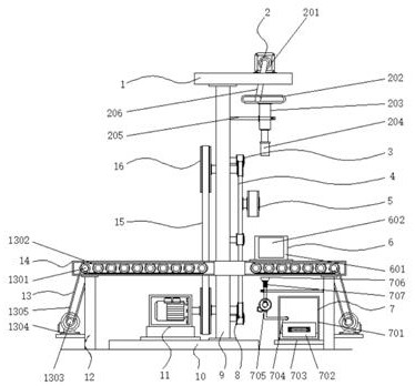
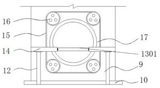
[0035] Example 1: See Figure 1-6 One metal thin film capacitor winding machine, including the bottom plate 10, one side of the top end of the bottom plate 10 fixedly connected to the vertical plate 9, the top end of the vertical panel 9 fixedly connected to the top plate 1, the top end of the top plate 1 is provided with a cutting mechanism 2, vertical On both sides of the plate 9 fixed to the table 14, the inner portion of the table 14 is provided with a conveying mechanism 13, and the two sides of the bottom end of the table 14 are fixedly connected to the leg 12, and the dust removal mechanism 7 is provided on one side of the bottom end of the table 14. On one side of the top end of the stage 14, a clamping limit mechanism 6 is provided, and the inner fixed connection between the vertical plate 9 is fixedly connected to the through hole 17, and the winding mechanism is provided on both sides of the through hole 17;

[0036] See Figure 1-6 One metal-based thin film capacitor win...

Embodiment 2

[0039] Example 2: The cutting mechanism 2 is composed of a first servo motor 201, a limiting block 202, a hydraulic telescoping rod 203, a cutting blade 204, a limit frame 205, and a restricted rod 206, and the first servo motor 201 fixedly connected to the top plate 1. On one side of the top, the model number of the first servo motor 201 can be an ACM. The output terminal of the first servo motor 201 is fixed to the top end of the shaft and the limit rod 206, and the bottom end activity of the limit rod 206 is in The interior of the limiting block 202, the limiting block 202 is disposed below the top plate 1, and the bottom end of the limit sleeve 202 is fixedly connected to the hydraulic telescopic rod 203, the model number of the hydraulic telescopic rod 203 can be SC200, hydraulic telescopic rod. The external portion of 203 is provided with a finite frame 205, and one side of the limit frame 205 is fixedly attached to one side of the tip end of the vertical plate 9, and the bo...

Embodiment 3

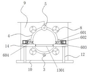
[0042] Example 3: The clamping limit mechanism 6 consists of a support seat 601, a hydraulic cylinder 602, a clamping block 603, and a retractable sleeve 604, and the support seat 601 is provided with two groups and two respectively coupled to two on the top of the table 14. At one end, one end of the support seat 601 is fixedly connected to the hydraulic cylinder 602, the model number of the hydraulic cylinder 602 can be SC, and the output terminal of the hydraulic cylinder 602 is fixed to the telescopic sleeve 604, and one end of the telescopic sleeve rod 604 is fixedly connected to the clamp block. 603, the clamping block 603 is semi-circular, and the clip block 603 regards the vertical centerline symmetry distribution of the vertical plate 9;

[0043] Specifically, such as figure 1 and figure 2 As shown, after the item is delivered to the specified position, the staff places a piece of article between the clamping block 603, activates the hydraulic cylinder 602, and the hydrau...


PUM


Abstract

The invention discloses a metallized film capacitor winding machine, specifically relates to the technical field of winding machines, comprising a bottom plate, one side of the top of the bottom plate is fixedly connected with a vertical plate, and the top of the vertical plate is fixedly connected with a top plate, so The top of the top plate is provided with a cutting mechanism, the two sides of the vertical plate are fixedly connected with a workbench, the inside of the workbench is provided with a conveying mechanism, the two sides of the bottom end of the workbench are fixedly connected with legs, and the workbench One side of the bottom end is provided with a dust removal mechanism, and one side of the top end of the workbench is provided with a clamping and limiting mechanism. The present invention is provided with a support seat, a hydraulic cylinder, a clamping block and a telescopic sleeve rod. When in use, after the item is transported to the designated position, the staff places the item between the clamping blocks, starts the hydraulic cylinder, and the hydraulic cylinder drives the expansion and contraction. The sleeve rods are stamped opposite to each other, so as to clamp and limit the items, which is convenient for the rolling of the items, and is suitable for clamping and limiting the items of different sizes, which improves the applicability of the equipment.

Description

Technical field [0001] The present invention relates to the field of winding machine, and is specifically a metallized thin film capacitor winder. Background technique [0002] At present, the capacitor is a main component that constitutes an electronic circuit. The film capacitor is made of overlapping the metal foil as the electrode and the plastic film, and it is generally made in a cylindrical shape, so the metallized thin film capacitor is during production and processing. It is necessary to use a winder. The existing metallized thin film capacitor winding machine still has some problems, the volume is complicated, the process has a lot of steps, more troublesome, thereby reducing the speed of product production. [0003] In the process of implementing the present invention, the inventors have found that there is at least the following problems in the prior art without being resolved: [0004] (1) Traditional metallized thin film capacitor winding machine, complicated rolls ...

Claims


Application Information

Patent Timeline
Patent Type & Authority Patents(China)
IPC IPC(8): H01G13/02H01G13/00
CPCH01G13/02H01G13/00
Inventor 罗通
Owner 新昌县杨辉网络科技有限公司
Why Eureka
Try Eureka