Steel bar cutting and packaging device for construction site

An on-site, steel bar technology, applied in the field of steel bar cutting and packing devices, can solve the problems of high labor intensity, inconvenient transportation, lack of steel bar auxiliary cutting, etc., and achieve the effect of improving efficiency and convenient transportation.

Active Publication Date: 2021-06-04
中建三局科创产业发展有限公司
View PDF7 Cites 0 Cited by
  • Summary
  • Abstract
  • Description
  • Claims
  • Application Information

AI Technical Summary

Problems solved by technology

[0005] The present invention provides a steel bar cutting and packaging device for construction sites, which can effectively solve the problem of lack of components for auxiliary cutting of steel bars proposed in the above background technology, resulting in inconvenient fixing of steel bars, resulting in high labor intensity and cutting at the same time The problem of inconvenient delivery

Method used


Image

  • Steel bar cutting and packaging device for construction site
  • Steel bar cutting and packaging device for construction site
  • Steel bar cutting and packaging device for construction site

Examples


Embodiment

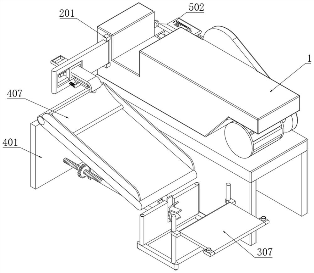
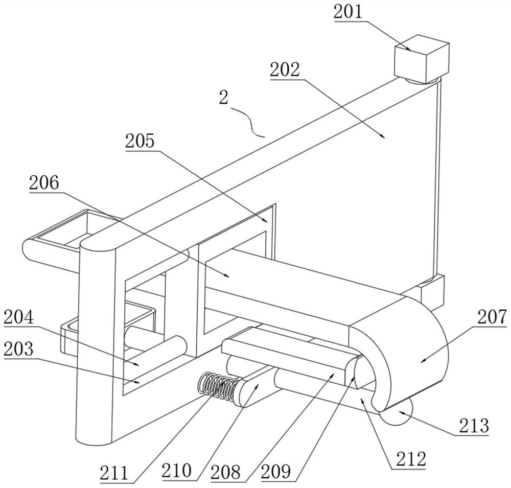
[0046] Example: such as Figure 1-8 As shown, the present invention provides a technical solution, a steel bar cutting and packaging device for construction sites, including a cutting machine body 1, an auxiliary mechanism 2 is installed at the bottom of one end of the cutting machine body 1, and the auxiliary mechanism 2 includes a fixed block 201, rotating plate 202, sliding hole 203, guide rod 204, sliding frame 205, connecting plate 206, limiting plate 207, support rod 208, limiting plate 209, vertical plate 210, contraction spring 211, slide bar 212 and rubber ball 213;

[0047] The bottom of one end of the cutting machine body 1 is symmetrically welded with a fixed block 201, the bottom of the fixed block 201 is rotated and embedded with a rotating plate 202, and one end of the rotating plate 202 is provided with a sliding hole 203, and the inner wall of the sliding hole 203 is symmetrically embedded with a guide rod 204, the outer end of the guide rod 204 is slidingly ...


PUM


Abstract

The invention discloses a steel bar cutting and packaging device for a construction site. An auxiliary mechanism is mounted at the bottom position of one end of a cutting machine body, the auxiliary mechanism comprises fixing blocks, a rotating plate, a sliding hole, a guide rod, a sliding frame, a connecting plate, a limiting plate, a supporting rod, a limiting plate, a mounting plate, a contraction spring, a sliding rod and a rubber ball, the fixing blocks are symmetrically welded to the bottom position of one end of the cutting machine body, the rotating plate is rotationally embedded into the bottom ends of the fixing blocks, and the sliding hole is formed in the side position of one end of the rotating plate. According to the steel bar cutting and packaging device, one side of a steel bar is conveniently limited, so that through the rotating plate, when the steel bar is cut, the steel bar is conveniently extruded and fixed by matching with the limiting plate, the steel bar is conveniently cut, and then the cutting efficiency is improved.

Description

technical field [0001] The invention relates to the field of construction site technology, in particular to a steel bar cutting and packing device used on the construction site. Background technique [0002] The construction site refers to the building construction, civil engineering, equipment installation, pipeline laying and other construction activities of industrial and civil projects, the approved construction site and the place where human beings carry out safe production, civilized work and construction. Cutting and packing of steel bars; [0003] For example, a steel bar cutting machine disclosed in the prior art, the application number is (201921151153.0), the patent: through the small deformation of the end of the steel bar, the cutting speed is fast and the processing efficiency is high; [0004] However, this patent lacks components for auxiliary cutting of steel bars, which makes it inconvenient to fix the steel bars, which makes labor intensive and inconvenie...

Claims


Application Information

Patent Timeline
Patent Type & Authority Applications(China)
IPC IPC(8): B21F11/00
CPCB21F11/00
Inventor 陈木根
Owner 中建三局科创产业发展有限公司
Why Eureka
Try Eureka