A clamping device for valve body end surface processing

An end face processing and clamping device technology, applied in positioning devices, metal processing equipment, metal processing mechanical parts, etc., can solve the problems of inconvenient processing work, inconvenient clamping, poor clamping effect, etc., and achieve good popularization. , easy to operate, good practical effect

Active Publication Date: 2021-09-03
广州市科阳机电阀门有限公司
View PDF15 Cites 0 Cited by
  • Summary
  • Abstract
  • Description
  • Claims
  • Application Information

AI Technical Summary

Problems solved by technology

[0003] And in the existing technology, the patent No. "CN201520476040.3" is "a fixture for processing the end surface of the valve body of the globe valve". In the process of processing the end surface of the valve body, the device only clamps the end surface of the valve body by pressing down. Because the shape of each end surface of the valve body is different, it is inconvenient for the device to clamp other end surfaces of the valve body, and the clamping effect is poor; and the device is inconvenient to rotate during processing, and it is inconvenient to perform better processing

Method used


Image

  • A clamping device for valve body end surface processing
  • A clamping device for valve body end surface processing
  • A clamping device for valve body end surface processing

Examples


Embodiment 1

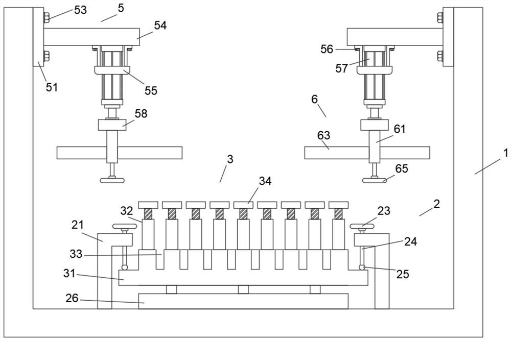
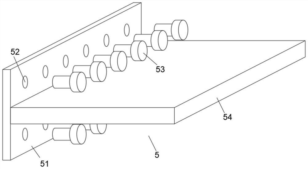
[0026] Embodiment 1: as Figure 1-6 As shown, this specific embodiment adopts the following technical solutions: a clamping device for valve body end surface processing, including a support frame 1, a rotation limiting mechanism 2 connected to the bottom of the support frame 1, and a fixing mechanism connected to the top of the rotation limiting mechanism 2 3. Two rows of connecting grooves 4 are dug through the top of the inner wall on both sides of the supporting frame 1, and the supporting frame 1 is respectively connected with supporting mechanisms 5 through the two rows of connecting grooves 4 on both sides, and the bottoms of the two supporting mechanisms 5 are connected with adjusting Agency 6;

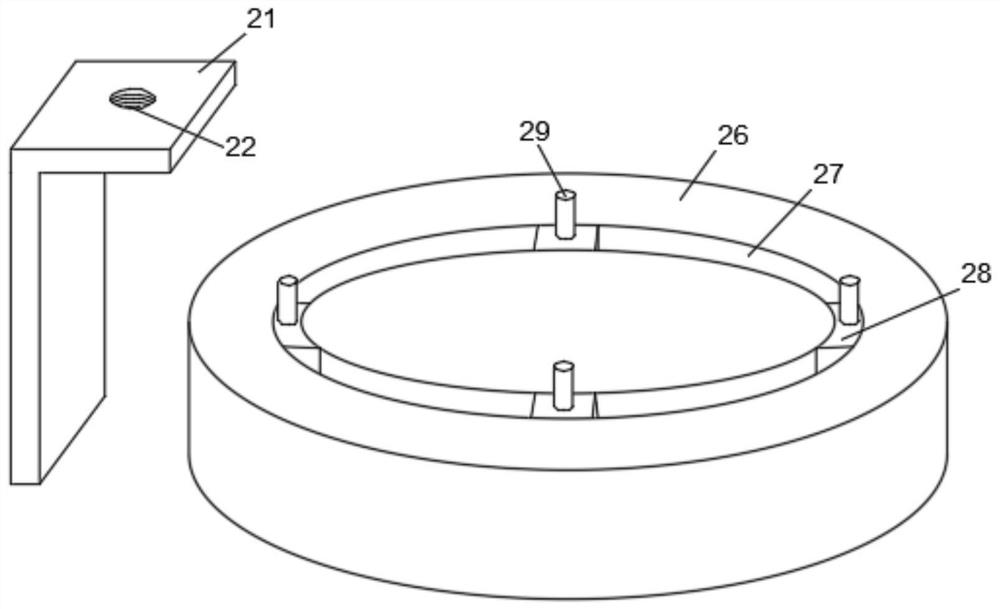
[0027] The rotation limiting mechanism 2 comprises two L plates 21, No. 1 thread groove 22, handle 23, threaded rod 24, No. 1 anti-slip block 25, base 26, chute 27, slide block 28 and support column 29, two L plates One end close to the top of 21 is drilled through a No. 1 thr...

Embodiment 2

[0038] Embodiment 2: In the present invention, the L plate 21, the No. 1 threaded groove 22, the handle 23, the threaded rod 24 and the No. 1 anti-skid block 25 can be replaced with two side plates, one end of the two side plates is connected to the supporting frame 1 through a torsion spring. The inner bottom end is connected, and the side walls of the other end of the two side plates are fixedly connected with anti-skid rubber pads. When rotating, the side plates are pulled open, and the side plates are rotated by the torsion spring. After turning the T-shaped seat 31, the side plates are released. The two side plates are reset by torsion springs, and the T-shaped seat 31 is limited by anti-skid pads.


PUM


Abstract

The invention discloses a clamping device for machining the end face of a valve body, comprising a support frame, a rotation limit mechanism is connected to the bottom of the support frame, a fixing mechanism is connected to the top of the rotation limit mechanism, and the top ends of the inner walls on both sides of the support frame are drilled through. There are two rows of connecting grooves, the support frame is respectively connected with supporting mechanisms through the two rows of connecting grooves on both sides, and the bottoms of the two supporting mechanisms are connected with adjusting machines. The valve body is clamped with the end face of one side of the flange plate, and it is convenient to clamp the flange plate on the valve body of different sizes; through the use of the rotating limit mechanism and the fixing mechanism, it is convenient to have the method. The flanged valve body rotates during the machining process, which is convenient to operate; through the combination of the support mechanism and the adjustment mechanism, it is convenient to insert the internal push-in limit on the two end faces of the valve body, which has good practicability and promotion. .

Description

technical field [0001] The invention belongs to the technical field of valve body processing, in particular to a clamping device for valve body end surface processing. Background technique [0002] In the process of processing the valve body, various processing equipment need to be used, and the processing equipment needs to use a large number of fixtures to clamp the valve body in the process of processing the valve body. [0003] And in the existing technology, the patent No. "CN201520476040.3" is "a fixture for processing the end surface of the valve body of the globe valve". In the process of processing the end surface of the valve body, the device only clamps the end surface of the valve body by pressing down. Because the shape of each end surface of the valve body is different, it is inconvenient for the device to clamp other end surfaces of the valve body, and the clamping effect is poor; and the device is inconvenient to rotate during processing, and it is inconvenie...

Claims


Application Information

Patent Timeline
Patent Type & Authority Patents(China)
IPC IPC(8): B23Q3/06
CPCB23Q3/062
Inventor 吕桂英
Owner 广州市科阳机电阀门有限公司
Why Eureka
Try Eureka