Detaching mechanism
A technology of dismantling parts and clamping jaws, which is applied in the directions of hand-held tools, workpiece clamping devices, manufacturing tools, etc., can solve the problems of low disassembly work efficiency, easy damage to the parts to be disassembled, etc., and achieves high work efficiency, not easy to damage, The effect of strong reliability
- Summary
- Abstract
- Description
- Claims
- Application Information
AI Technical Summary
Problems solved by technology
Method used
Image

Examples
Embodiment Construction
[0022] In order to make the technical problems solved by the present invention, the technical solutions adopted and the technical effects achieved clearer, the technical solutions of the present invention will be further described below in conjunction with the accompanying drawings and through specific implementation methods.
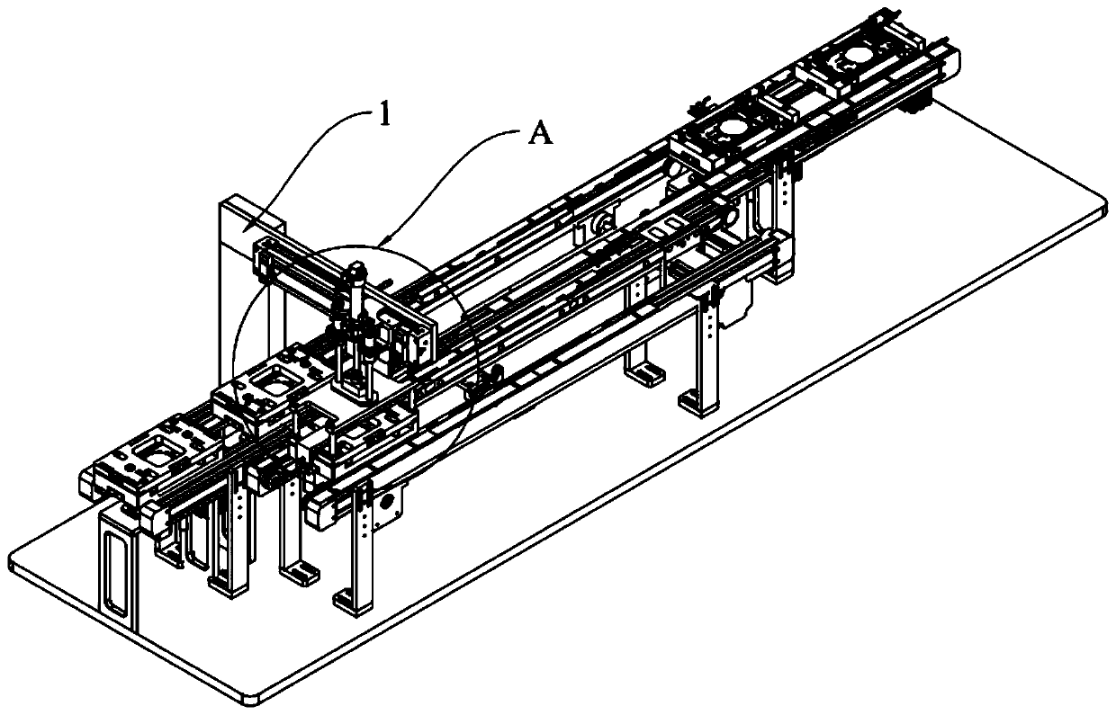
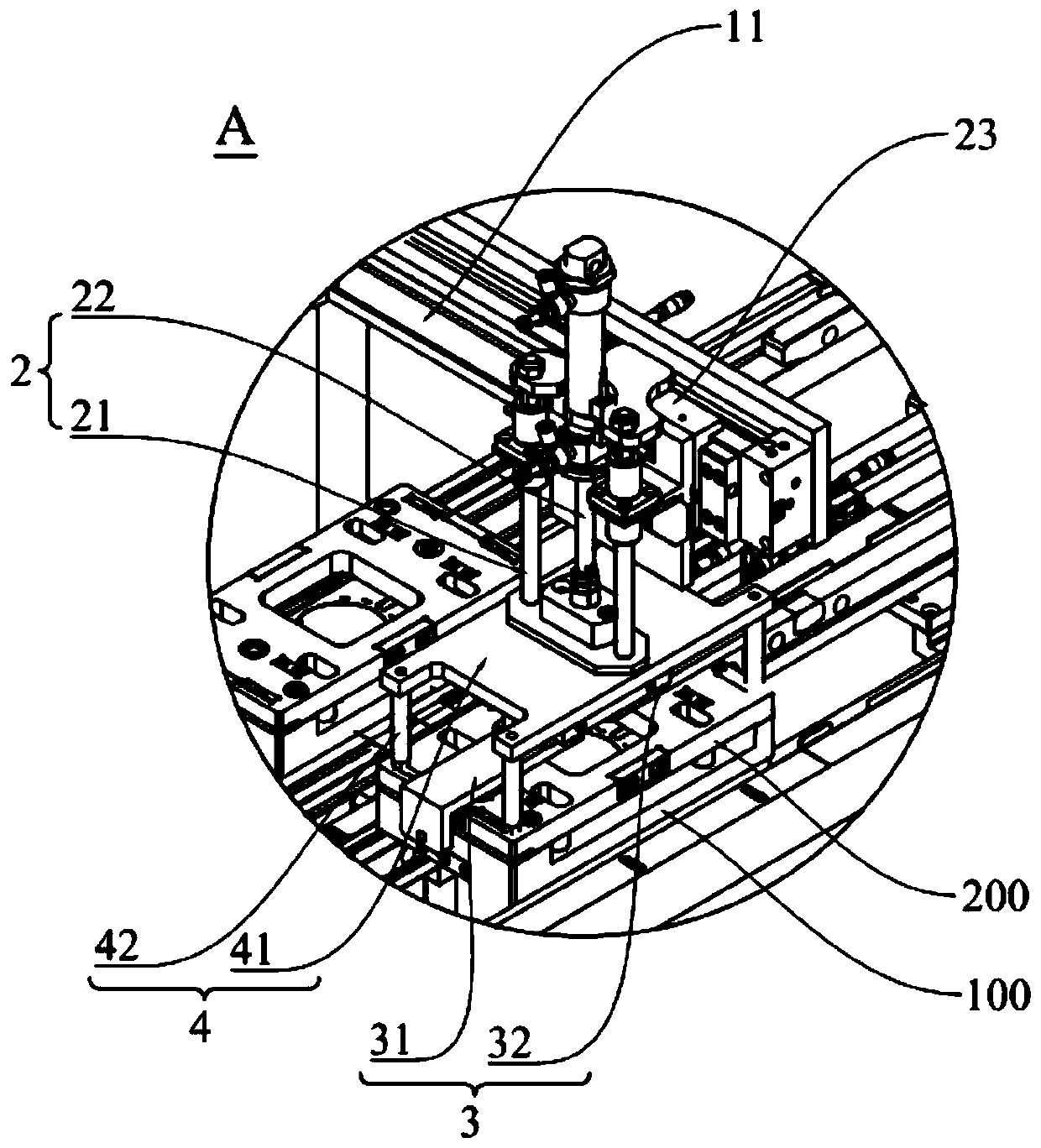
[0023] Such as figure 1 and figure 2 As shown, a disassembly mechanism includes a support frame 1, a lifting assembly 2, a jaw assembly 3 and an unlocking assembly 4. One end of the lifting assembly 2 is movably arranged on the supporting frame 1, and the other end is arranged on the unlocking assembly 4. The assembly 2 can move in the vertical direction, and the jaw assembly 3 for grasping the part 200 to be disassembled is arranged on the unlocking assembly 4. The unlocking assembly 4 can lock the part 200 to be disassembled on the carrier 100 or make the part to be disassembled 200 unlocked from 100 vehicles.
[0024] It can be understood that, si...
PUM
 Abstract
Description
Claims
Application Information
 - Generate Ideas
- Intellectual Property
- Life Sciences
- Materials
- Tech Scout
- Unparalleled Data Quality
- Higher Quality Content
- 60% Fewer Hallucinations
Browse by: Latest US Patents, China's latest patents, Technical Efficacy Thesaurus, Application Domain, Technology Topic, Popular Technical Reports.
© 2025 PatSnap. All rights reserved.Legal|Privacy policy|Modern Slavery Act Transparency Statement|Sitemap|About US| Contact US: help@patsnap.com