
Assembly type stiff concrete shear wall structure with embedded connecting steel plate and manufacturing method thereof

A technology for concrete shear walls and connecting steel plates, which is applied to walls, building components, building structures, etc., can solve the problems of unfavorable assembly and limit the use height of shear wall structures, and achieve simple and easy operation steps and shorten The effect of construction period and convenient operation

Active Publication Date: 2020-08-11
CSIC INT ENG CO LTD +4
View PDF7 Cites 1 Cited by
  • Summary
  • Abstract
  • Description
  • Claims
  • Application Information

AI Technical Summary

Problems solved by technology

In today's prefabricated buildings, the most used and most mature technology is the assembly of frame structures, but the assembly of shear walls often used in high-rise buildings or super high-rise buildings still has quite a lot of problems to be solved. Therefore, the current relevant industry regulations limit the use height of shear wall structures in prefabricated buildings, and even stipulate that prefabricated structures should not be used for core tube structures in super high-rise buildings.

Method used


Image

  • Assembly type stiff concrete shear wall structure with embedded connecting steel plate and manufacturing method thereof
  • Assembly type stiff concrete shear wall structure with embedded connecting steel plate and manufacturing method thereof
  • Assembly type stiff concrete shear wall structure with embedded connecting steel plate and manufacturing method thereof

Examples


Embodiment Construction

[0048] In order to make the purposes, technical solutions and advantages of the embodiments of the present invention more clearly understood, the embodiments of the present invention will be further described in detail below with reference to the embodiments and the accompanying drawings. Here, the exemplary embodiments of the present invention and their descriptions are used to explain the present invention, but not to limit the present invention.

[0049] In the description of the present invention, it is to be understood that the terms "comprising / comprising", "consisting of" or any other variation thereof are intended to encompass a non-exclusive inclusion such that a product, device, A process or method includes not only those elements, but may also include other elements, if desired, not expressly listed, or elements inherent to the product, device, process, or method. Without further limitation, an element defined by the phrases "comprising / comprising", "consisting of" ...


PUM


Abstract

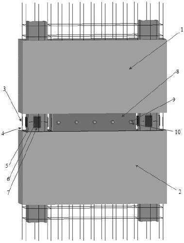
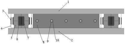
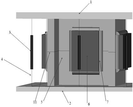
The invention provides an assembly type stiff concrete shear wall structure with an embedded connecting steel plate and a manufacturing method thereof. The assembly type stiff concrete shear wall structure with the embedded connecting steel plate comprises edge profile steel, edge stress longitudinal bars, the embedded connecting steel plate, embedded connecting concrete, grouting sleeves and thelike; under the state that an upper-layer shear wallboard and a lower-layer shear wallboard are connected and assembled, the edge stress longitudinal bars of the lower-layer shear wallboard are inserted into the grouting sleeves corresponding to the upper-layer shear wallboard, and grouting is conducted in the grouting sleeves; the embedded connecting concrete at the bottom of the upper-layer shear wallboard and the embedded connecting steel plate at the top of the lower-layer shear wallboard are mutually embedded and fixedly connected through high-strength bolts, and the edge profile steel ofthe upper-layer shear wallboard and the edge profile steel of the lower-layer shear wallboard are welded and fixed. The shear wall structure has the advantages of high lateral stiffness, high bearingcapacity, simplicity and feasibility in connection of horizontal joints between walls, high reliability, clear force transmission path, small on-site wet working amount, high universality and the like, and can be widely applied to high-rise or super high-rise fabricated buildings.

Description

technical field [0001] The present invention generally relates to the field of building structure engineering, and mainly relates to a prefabricated rigid concrete shear wall structure with embedded connecting steel plates and a manufacturing method thereof, which can be specifically applied to prefabricated rigid concrete structures. Background technique [0002] Prefabricated buildings are currently a hot research issue in the field of construction, and they are also the direction of future development of the construction industry. The strength and stiffness of components and the connection between components are the key to prefabricated buildings. In today's prefabricated buildings, the most used and most mature technology is the assembly of frame structures, but the assembly of shear walls often used in high-rise buildings or super high-rise buildings still has quite a lot of problems to be solved. Therefore, the current relevant industry regulations limit the use heigh...

Claims


Application Information

Patent Timeline
IPC IPC(8): E04C2/06E04C2/04E04C2/38E04B1/61E04B2/68
CPCE04B1/6141E04B2/68E04B2001/6191E04C2/044E04C2/06E04C2/384
Inventor 兰涛秦广冲傅彦青常好诵剧锦三门进杰李然樊冠磊赵钿杨运杰
Owner CSIC INT ENG CO LTD
Learn More