Eureka AIR delivers breakthrough ideas for toughest innovation challenges, trusted by R&D personnel around the world.

Experimental device for adjustable frequency and phase unsteady flow control based on rotating slot grid

A technology for unsteady flow and control experiments, applied in pump control, measuring devices, aerodynamic tests, etc., to achieve the effects of small volume and weight, improved boosting capacity, and adjustable phase

Active Publication Date: 2021-06-08
NANJING UNIV OF AERONAUTICS & ASTRONAUTICS
View PDF0 Cites 0 Cited by
  • Summary
  • Abstract
  • Description
  • Claims
  • Application Information

AI Technical Summary

Problems solved by technology

2. Phase control device problem

Method used


Image

  • Experimental device for adjustable frequency and phase unsteady flow control based on rotating slot grid
  • Experimental device for adjustable frequency and phase unsteady flow control based on rotating slot grid
  • Experimental device for adjustable frequency and phase unsteady flow control based on rotating slot grid

Examples


Embodiment 1

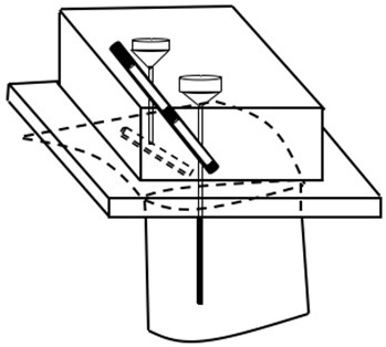
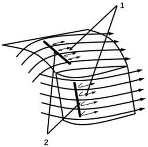
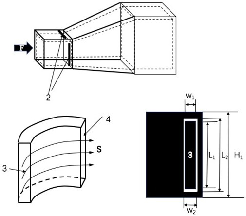
[0041] Using the above-mentioned inventive device, research on the unsteady control of the corner separation flow of the double-sided diffuser channel has been carried out, such as Figure 5 , There is a 1mm jet slit at the initial separation position of the two expansion sections. Among them, the pipeline of bleed air is intersected with a rotating slot grid driven by a high-speed micro motor. There are a total of 6 slots distributed on the rotating slot grid, of which the upper part of the rotating slot grid (including 3 slots) and The intersecting air channel leads to the jet outlet on one side of the expansion channel, and the lower half of the intersecting air channel is connected to the jet outlet on the other side. The micro motor drives the rotating slit grid to rotate to generate periodic opening and closing flow. The path, and then form a periodic pulse jet, and control the phase of the jet in the corner area by designing the staggered positions of the distributed sl...

Embodiment 2

[0043] Using the above-mentioned inventive device, the research on unsteady control of the separation flow in the corner area of ​​the double-sided diffuser channel with the different number of openings of the slit grid was carried out at the same time, and a jet slit of 1 mm was also opened at the initial separation position of the two expansion sections. The pipeline of the same bleed air is intersected with a rotating slit grid driven by a high-speed micro-motor. The difference is that three slits are used in the upper part, and two slits are used in the lower part, in which the upper part of the rotating slit grid (including 3 slits) intersects with the air channel leading to the jet outlet on one side of the expansion channel. The air path intersected with the lower part (including 2 slits) is connected to the jet outlet on the other side, and the micro motor drives the rotating slit grid to rotate to generate periodic opening and closing flow paths, thereby forming period...


PUM


Abstract

The invention relates to an experimental device for adjustable frequency and phase unsteady flow control based on a rotating slit grid, comprising an air inlet, a slit grid inlet flow path, a rotating slit grid, a slit grid outlet flow path, a driving slit grid rotation generator, and a control Jet spout. Through the design of the bleed flow path, the external high-pressure gas is introduced into the jet nozzles on both sides of the corner area, and the slit grid with a certain phase difference is driven to rotate by driving the slit grid rotation generator, and a pulse jet is generated at the jet outlet, and the interaction between the pulse jet and the flow field is used. The effect is to suppress the separation flow, so as to reduce or weaken the separation in the corner area. Advantages: The device of the present invention can achieve phase-adjustable flow excitations of different frequencies through the advantage of the phase difference of the slit grid under the condition of asymmetric flow separation in the corner area. This small unsteady control excitation can rely on a large Small jet volumes produce significantly controlled flow separation. The phase of the device is adjustable, the frequency is controllable, the structure is simple, the volume and weight are small, and the working performance is reliable.

Description

technical field [0001] The invention is an experimental device for controlling unsteady flow with adjustable frequency and phase based on a rotating slot grid, and belongs to the technical field of air compressors. Background technique [0002] The technical level of aero-engines plays an extremely important role in the development of national defense weapons and even national security and strategy. It is an important symbol to measure a country's comprehensive industrial level and scientific and technological strength, and has been dubbed the "Pearl in the Crown of Modern Industry". The compression capacity and efficiency of the compressor fundamentally determine the overall performance level of the aero-engine, and are an important indicator of fluid mechanical performance. With the increase of the single-stage load of the compressor, it is very easy to cause the separation of the boundary layer on the suction surface of the compressor blade, the separation of the corner a...

Claims


Application Information

Patent Timeline
Patent Type & Authority Patents(China)
IPC IPC(8): G01M9/02G01M9/04F04D27/00
CPCF04D27/001G01M9/02G01M9/04
Inventor 黄国平杜爽王进春杨雨轩袁伟豪
Owner NANJING UNIV OF AERONAUTICS & ASTRONAUTICS
Why Eureka
Eureka Blog
Learn More