Synchronous after flow ventilating compressor

A technology of air compressor and air flow channel, which is applied in the field of synchronous backflow ventilation compressor, and can solve the problems of unfavorable environmental protection, inability to save energy, low mechanical efficiency, etc.

Inactive Publication Date: 2009-10-28
林钧浩
View PDF0 Cites 8 Cited by
  • Summary
  • Abstract
  • Description
  • Claims
  • Application Information

AI Technical Summary

Problems solved by technology

[0002] Various ventilators, air compressors, gas compressors, etc. that people use now have poor pressurization effects and low mechanical efficiency, which can neither save energy nor be conducive to environmental protection.

Method used


Image

  • Synchronous after flow ventilating compressor
  • Synchronous after flow ventilating compressor
  • Synchronous after flow ventilating compressor

Examples


Embodiment 1

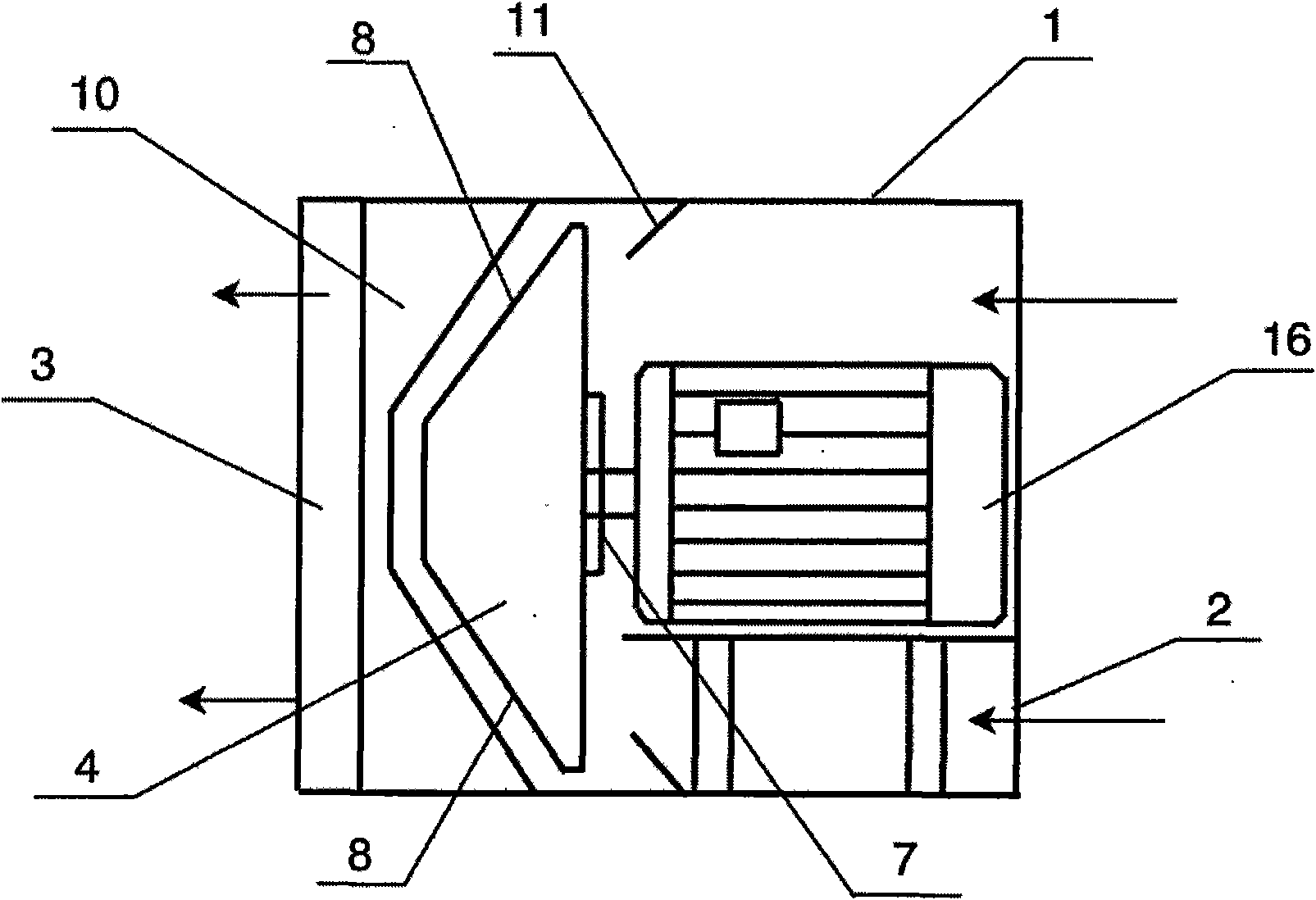
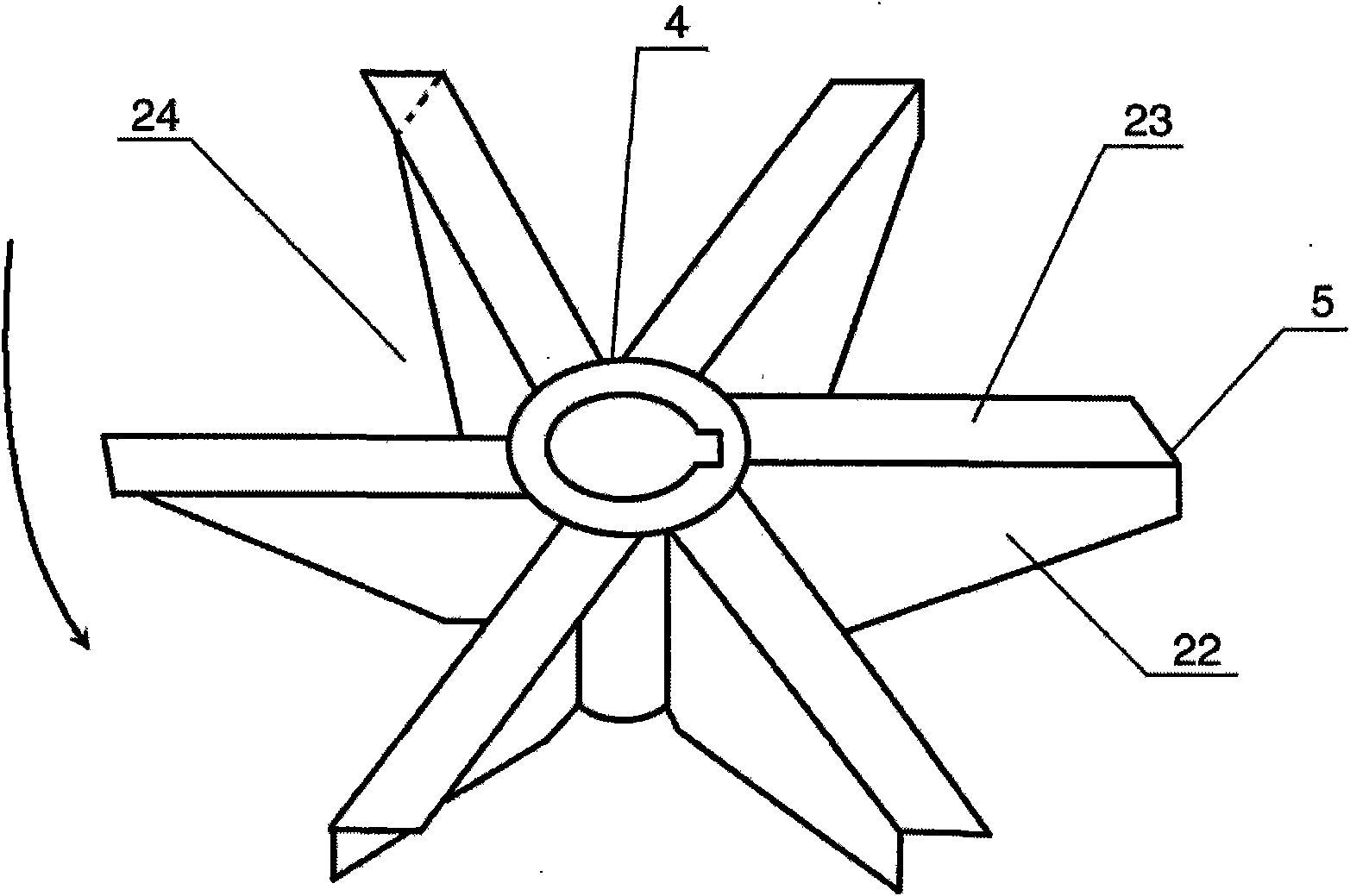
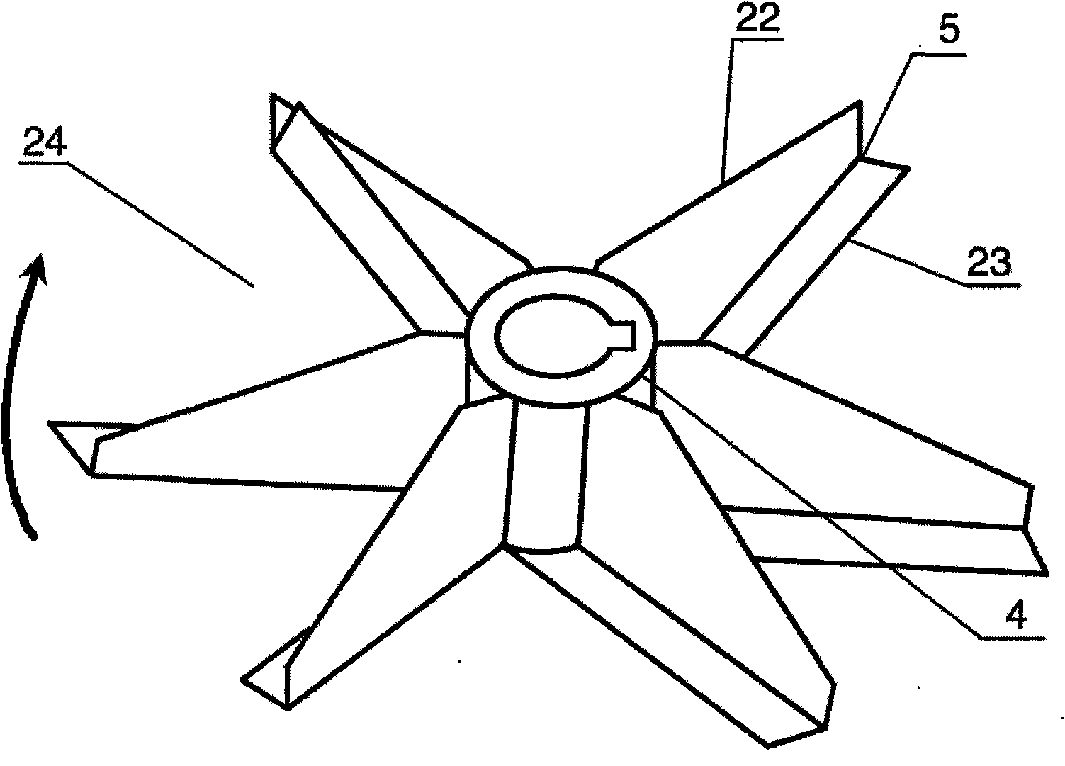
[0067] Embodiment 1 (with reference to figure 1 , figure 2 , image 3 ), a synchronous post-flow ventilation compressor, including a cylindrical shell structure 1, a casing air inlet 2, a casing air outlet 3, an impeller 4 made of double-walled impeller blades, and a double-walled impeller blade 5 (including a negative pressure Partition wall 23, thrust wall 22), impeller blade disc 7, the impeller blade 5 is not provided with a negative pressure partition wall on the axial rear side, and the axial front side is provided with a negative pressure partition wall 23, and the entire blade is radially from front to back along the impeller, From the rear of the shaft to the front of the shaft, it gradually inclines and shrinks and narrows. The rear axial side of the impeller becomes a high middle and low structure shape around the periphery. Air outlet 8. The casing axial outlet deflector 10 connected to the casing side wall is arranged outside the rear axial direction of the im...

Embodiment 2

[0071] Embodiment 2 (with reference to Figure 4 , figure 2 , image 3 ), a synchronous backflow ventilation compressor, this example is basically the same as Example 1, the difference is that this example is a unified rotor formed by connecting four impellers of the same structure in series with the same drive shaft, and the rotor is assembled in a cylindrical tube In the casing, the casing axial inlet deflector 29 is installed at the air inlet of the casing, the casing axial outlet deflector 10 is installed at the casing outlet, and the entire rotor is driven by the motor through the coupling 18 and the transmission shaft. 28 drive rotation; the second difference is that the front side of the impeller blade shaft of the four impellers in this example is inclined to the front of the impeller shaft, and the front shaft of the impeller is high around the middle depression on the side; the impeller blades are from front to back along the radial direction of the impeller Gradu...

Embodiment 3

[0075] Embodiment 3 (with reference to Figure 5 , Figure 6 , Figure 7 ), a synchronous backflow ventilation compressor, this example is basically the same as Example 1, the difference is that the casing of this example is a combination of cylindrical and spiral casings, that is, the front half is cylindrical, and two impellers are installed inside it , the second half is a spiral casing, and an impeller is installed inside it. The air outlet 3 of the casing is arranged on the radial edge of the spiral casing, and the outlet direction is radial; The outer side of the outlet end of the air inlet 2 of the shell is provided with a horn-shaped diffuser 20 that expands from front to back, and the outer side of the diffuser 20 is provided with a connecting deflector 21, and the diffuser 20 connects the deflector 21 with the air inlet 2 of the casing Inner wall connection. The second difference is that the impeller of this example is a synchronous backflow fan impeller, the imp...


PUM


Abstract

The invention discloses a synchronous after flow ventilating compressor, which comprises a shell, an air inlet of the shell, an outlet of the shell, an impeller, impeller blades, an airflow channel inside the impeller, a blisk of the impeller. The compressor is characterized in that the axial back sides of the impeller blades gradually axially tilt along the radial direction of the impeller from front to back towards the axial direction of the impeller; the axial back side of the impeller gradually axially tilts along the radial direction of the impeller from front to back towards the axial direction of the impeller; and gradually and axially tilting part of the axial direction back side of the impeller is provided with an axial air outlet of the impeller. Compared with the prior art, the compressor has the advantages of simple structure, small volume, few materials, light weight, convenient transportation and mounting, resources, saving good pressurized effect, high efficiency, energy saving, low noise, favorability for environment protection and the like.

Description

technical field [0001] The invention relates to a synchronous backflow ventilation compressor, which belongs to the technical field of air purification and compression. Background technique [0002] The various ventilators, air compressors, and gas compressors used by people now have poor pressurization effects and low mechanical efficiency, which can neither save energy nor be conducive to environmental protection. Contents of the invention [0003] The purpose of the present invention is to overcome the above-mentioned shortcoming of prior art, and provide a kind of synchronous afterflow ventilation compressor that can make various fans, compressors, gas compressors etc. efficient, save energy, noise is low. [0004] The purpose of the present invention can be achieved through the following technical measures: a synchronous post-flow ventilation compressor, including an organic casing, a casing air inlet, a casing air outlet, an impeller, an impeller blade, an inner air ...

Claims


Application Information

Patent Timeline
Patent Type & Authority Applications(China)
IPC IPC(8): F04D19/00F04D29/38F04D29/32F04D29/54
Inventor 林钧浩
Owner 林钧浩
Why Eureka
Try Eureka