Rolling gear of turbine

A cranking device and steam turbine technology, applied to mechanical equipment, engine components, machines/engines, etc., can solve problems such as limited reduction ratio, potential safety hazards, and large geometric dimensions, so as to improve transmission efficiency, eliminate potential safety hazards, and geometrically small size effect

Inactive Publication Date: 2009-01-14
DONGFANG TURBINE CO LTD
View PDF0 Cites 11 Cited by
  • Summary
  • Abstract
  • Description
  • Claims
  • Application Information

AI Technical Summary

Problems solved by technology

The reduction ratio of the worm gear / worm or sprocket is still limited, and the efficiency of the reduction transmission is not high, so that the number of stages of the following spur gear reduction transmission pair is large (generally six), the structure of the reducer is not compact, and the geometric size is large , takes up a lot of space
[0005] 2. The deceleration and transmission pairs at all levels are rigidly matched without buffer function. When the swing gear is put in, it will collide, make noise, and easily damage the gear
[0006] 3. The oscillating gear is arranged above the rotor and input tangentially from the top, which has potential safety hazards. When the cranking device fails, the oscillating gear falls and is mis-injected, which will cause major equipment accidents
[0007] 4. The bearings of the oscillating gear and the spur gear are sliding bearings, which have a large wear and tear, resulting in poor meshing of the gears, high noise and short service life

Method used


Image

  • Rolling gear of turbine
  • Rolling gear of turbine
  • Rolling gear of turbine

Examples


Embodiment Construction

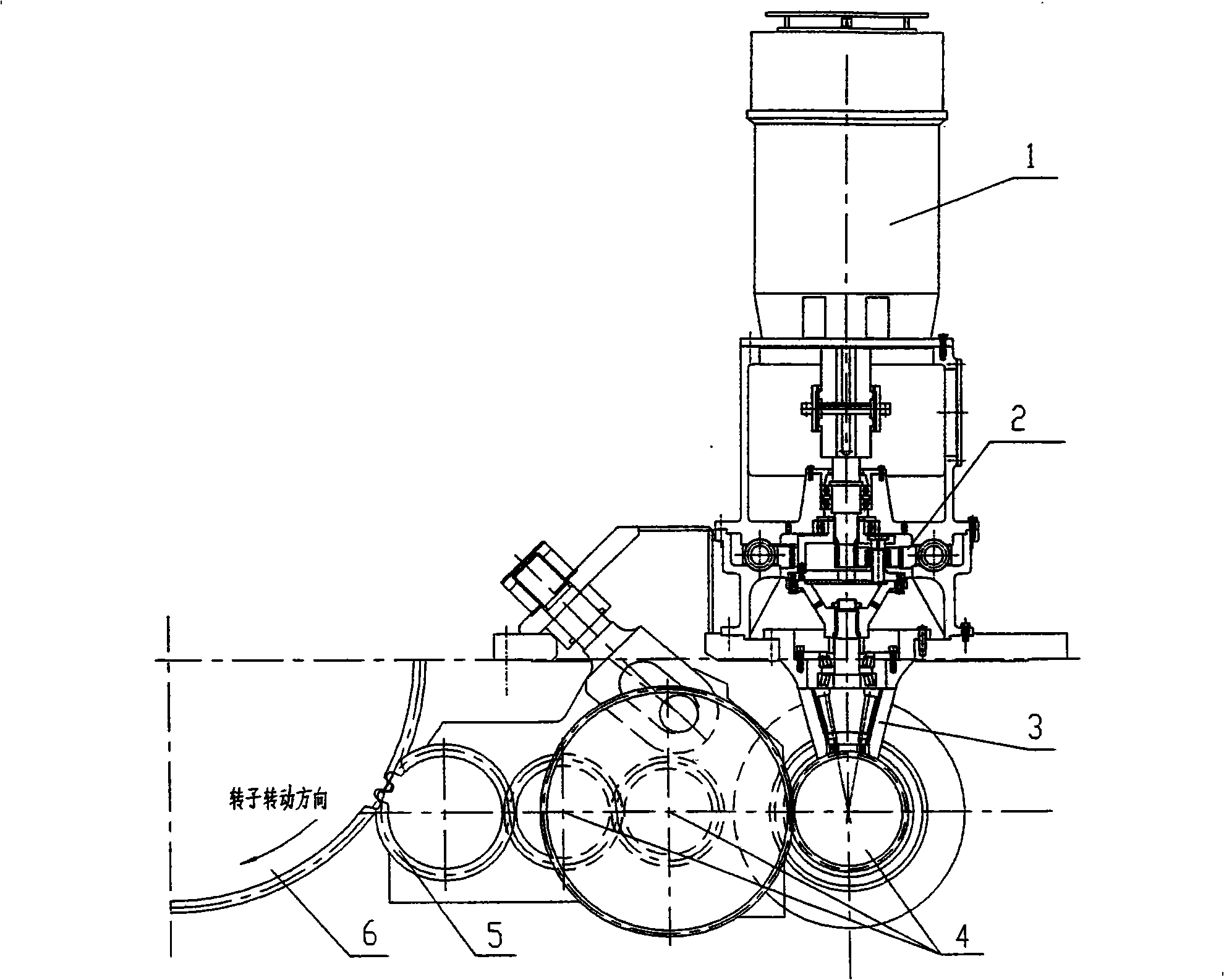
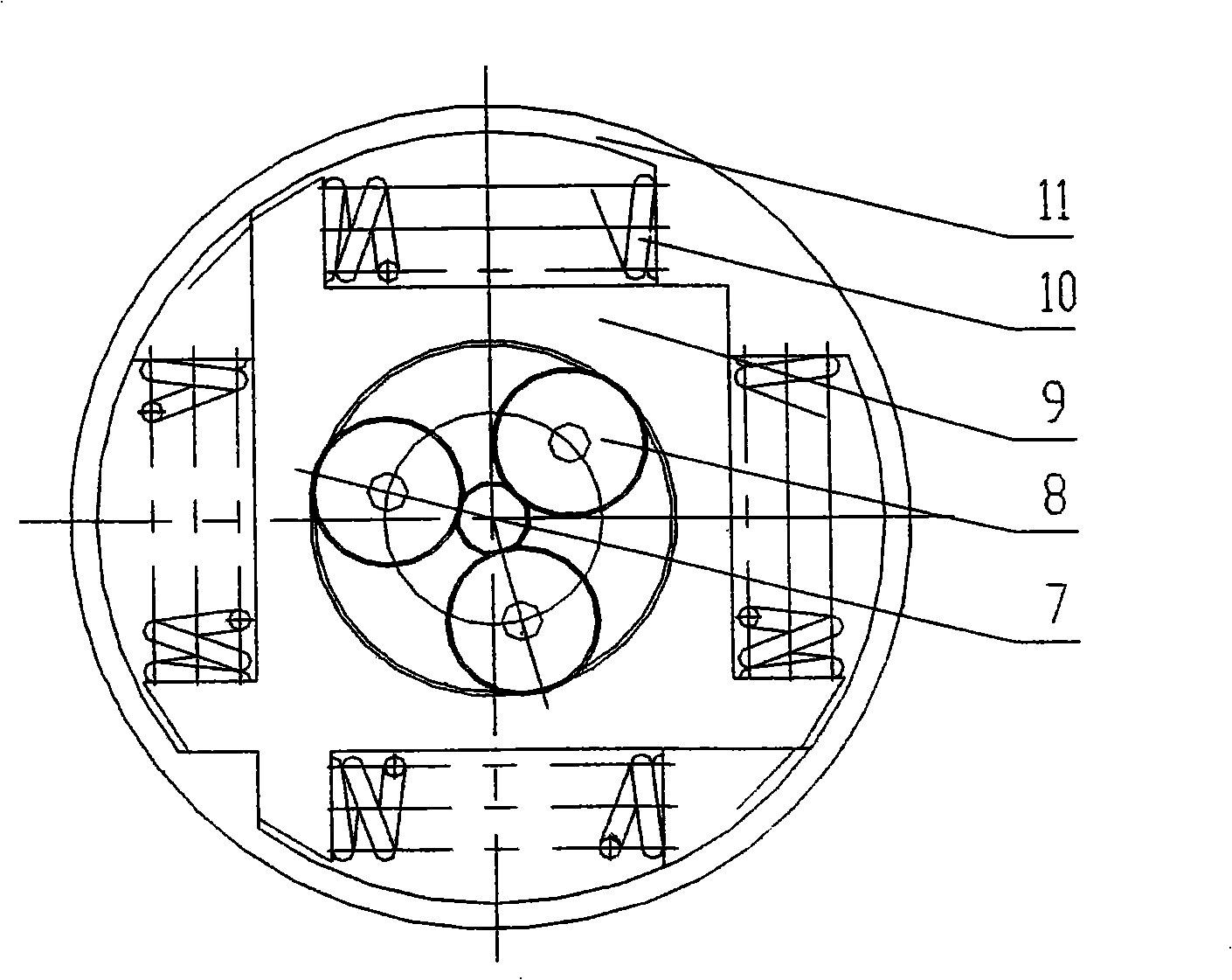
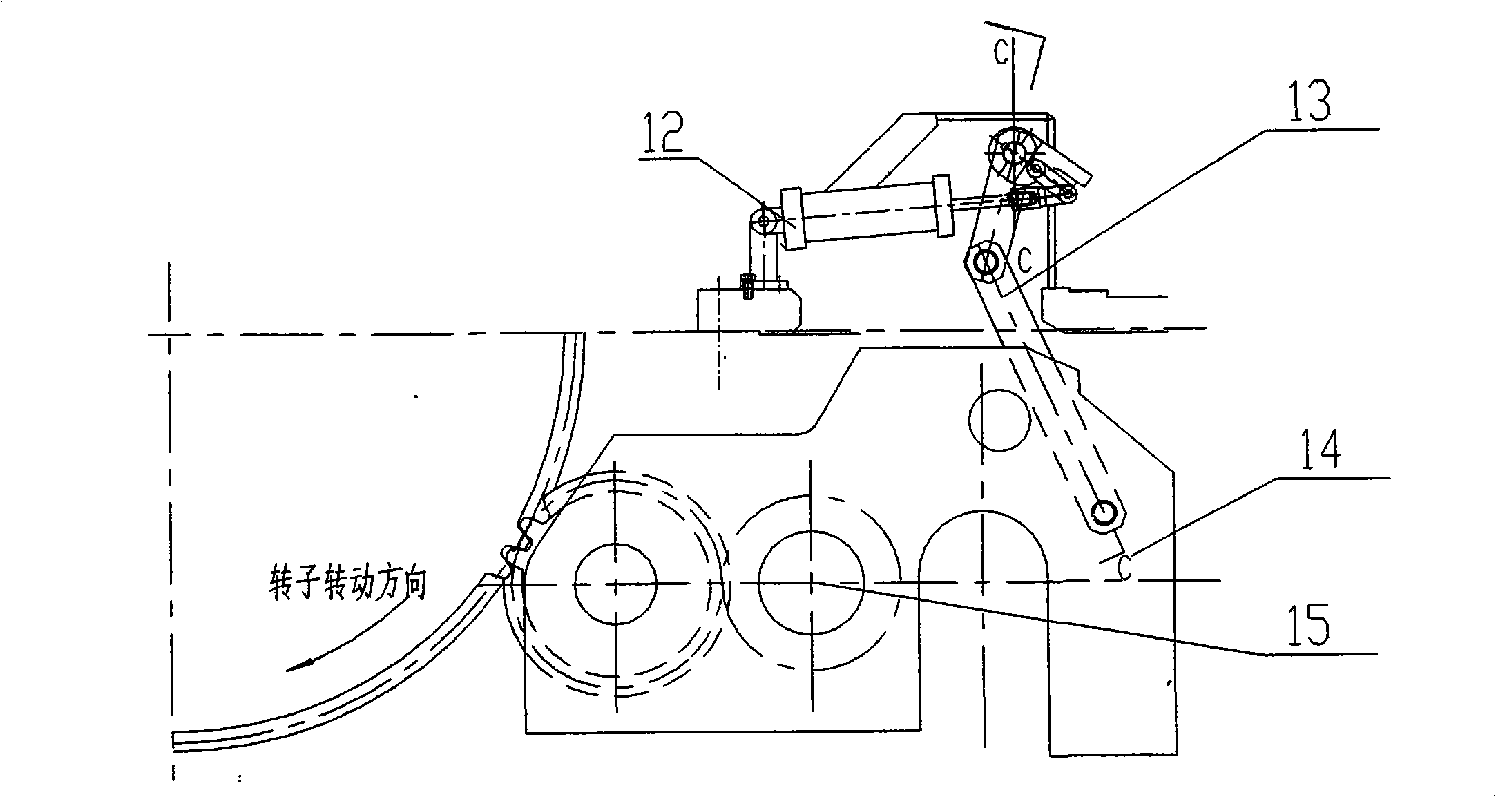
[0029] see figure 1 : This device comprises drive motor 1, planetary gear transmission box 2, bevel gear transmission pair 3, parallel shaft gear reduction transmission pair 4, swing gear 5, ring gear 6, and the clutch mechanism of swing gear 5 connected in sequence. Among them: the large ring gear 5 is arranged on the rotor of the steam turbine; the driving motor 1 and the star gear transmission box 2 are arranged vertically above the parallel shaft gear reduction transmission pair 4, and are connected with the parallel shaft gear reduction transmission pair 4 through the bevel gear transmission pair 3 , to change the direction of power transmission.

[0030] Compared with the traditional worm gear / worm or sprocket, the star gear transmission box has a larger reduction ratio, which reduces the number of stages of the parallel shaft gear reduction transmission pair. This device only uses 4 parallel shaft gear reduction transmission pairs, which is The requirement of 2r / min is...


PUM


Abstract

The invention discloses a turning gear of a steam turbine, comprising a driving motor, a reducer, a swinging gear, a large tooth ring and a clutch mechanism of the swinging gear which are connected in sequence; the large tooth ring is arranged on a rotor of the steam turbine and the reducer is provided with a multilevel speed-reducing transmission pair; the first-level speed-reducing transmission pair of the reducer is a planetary gear transmission box, a second-level speed-reducing transmission pair is an umbrella gear transmission pair and the rest is a planar gear speed-reducing transmission pair; a buffering spring is arranged between an inner tooth ring of the planetary gear transmission box and the box; the bearings of the swinging gear and the planar gear are rolling bearings; the swinging gear is positioned below the middle section of the rotor of the steam turbine and is corresponding to the large tooth ring in a tangential mode. The invention has the advantages of compact structure and small occupied area and has the buffering function with safety and reliability and without miscarriage when in use.

Description

technical field [0001] The present invention relates to a steam turbine, in particular to its barring device. Background technique [0002] Before starting and after stopping, the steam turbine generator set needs to keep running at a low speed to avoid the rotor bending caused by the temperature difference between the upper and lower cylinders of the cylinder. The low speed running state is realized by the cranking device. The barring device is usually driven by a motor, decelerated by a reducer, and the swing gear meshes with the large ring gear arranged on the rotor of the steam turbine to drive the rotor to rotate. When the rotor of the steam turbine reaches a certain rotational speed, the swing gear is thrown away and separated from the rotor. [0003] There are also some disadvantages in the existing turning gear, mainly: [0004] 1. Since the cranking speed is very low, only 2r / min, the reduction ratio of the reducer is required to be particularly large. In order to...

Claims


Application Information

Patent Timeline
Patent Type & Authority Applications(China)
IPC IPC(8): F01D25/34F01D25/36
Inventor 陈晓明王建伟强宏志余宏才唐清舟袁永强王建录方宇商宇唐礼周永东黄建强
Owner DONGFANG TURBINE CO LTD
Why Eureka
Try Eureka