

Air separation system for recycling waste heat of compressed air
An air separation system and compressed air technology, applied in the field of air separation system, can solve the problem of not taking into account the high relative humidity of the air, etc., and achieve the effects of increasing the pressure ratio, saving energy, and reducing the cost of the system
- Summary
- Abstract
- Description
- Claims
- Application Information
AI Technical Summary
Problems solved by technology
Method used
Image

Examples
Embodiment Construction
[0038] The present invention will be described in further detail below in conjunction with the accompanying drawings and embodiments.
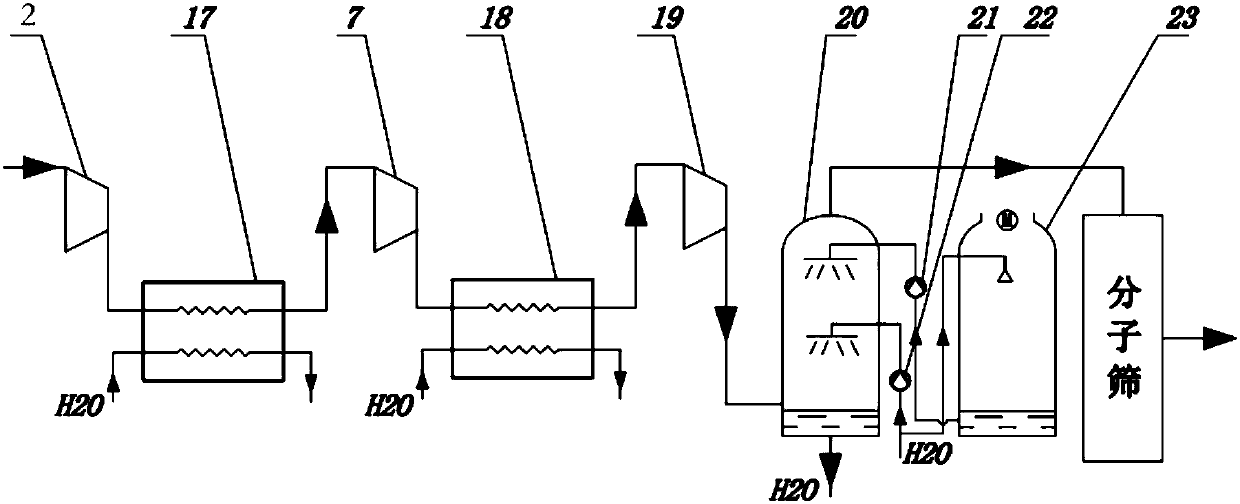
[0039] Such as figure 1As shown, in the air separation system of the prior art, the raw material air after coarse filtering of large particles by the filter first enters the primary air compressor 2, and enters the first water cooler 17 after heating up and increasing the pressure, and enters the secondary air after cooling down to about 40°C. The compressor 7 continues to compress, and the compressed air from the outlet of the secondary air compressor enters the second water cooler 18 to cool down to about 40°C, and then enters the third-stage air roller 19. The high-temperature and high-pressure gas at the outlet of the third-stage air compressor 19 enters the air cooling tower 20 for cooling and dehumidification It becomes a saturated gas with a temperature of about 15°C, and then enters the molecular sieve to complete the subsequent steps....
PUM
 Abstract
Description
Claims
Application Information