
An AC distribution box based on wind force opening and closing for heat dissipation

A box and shaft technology, applied in substation/power distribution device housing, electrical components, substation/switch layout details, etc., can solve problems such as simple structure of heat dissipation holes, burnout of components, affecting heat dissipation of components, etc., to achieve improved The effect of the cleaning effect

Active Publication Date: 2021-12-07
XINDIAN ELECTRIC GRP CO LTD
View PDF0 Cites 0 Cited by
  • Summary
  • Abstract
  • Description
  • Claims
  • Application Information

AI Technical Summary

Problems solved by technology

[0002] Since there are a large number of components such as power and communication equipment, circuit breakers, and frequency converters installed inside the power distribution cabinet, when the outdoor temperature is too high, and a large amount of heat generated during its own operation, the internal temperature of the power distribution cabinet will rise. , When the internal temperature of the power distribution cabinet is too high, it will affect its operation stability and service life. In severe cases, it will also cause components to burn out and cause other accidents.
[0003] In general, cooling holes are installed on the power distribution cabinet for heat dissipation and cooling. However, the structure of these cooling holes is simple, and foreign dust and other sundries will also enter the cabinet, causing the surface of components to stick due to electrostatic adsorption and other effects. A large amount of dust is attached to it, which will corrode the components after accumulating over time, and also affect the heat dissipation effect of the components, affecting the normal operation of the power distribution cabinet

Method used


Image

  • An AC distribution box based on wind force opening and closing for heat dissipation
  • An AC distribution box based on wind force opening and closing for heat dissipation
  • An AC distribution box based on wind force opening and closing for heat dissipation

Examples


Embodiment

[0025] as attached figure 1 to attach image 3 Shown:

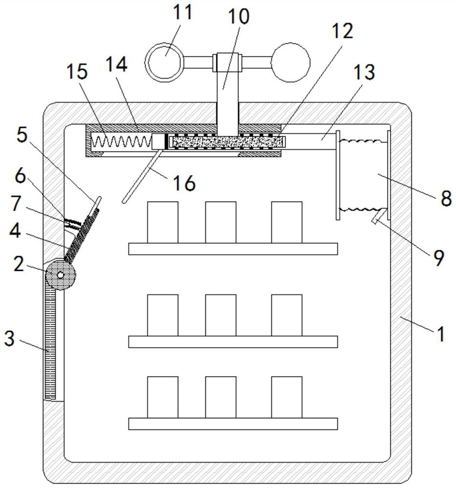
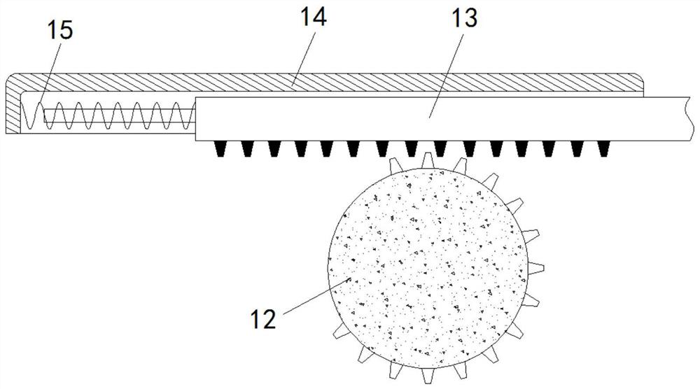
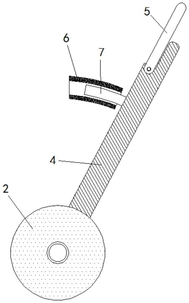
[0026] The invention provides an AC power distribution box based on wind force opening and closing for heat dissipation, which includes a box body 1, the left side of the box body 1 is rotatably connected with a rotating shaft 2, the bottom of the rotating shaft 2 is fixed with a filter screen 3, and the upper right side of the rotating shaft 2 is fixed The dial 4 is connected, the upper end of the dial 4 is hinged with a movable plate 5, the inner left wall of the box body 1 is fixedly connected with an aluminum ring 6, and the left side of the dial 4 is fixedly connected with a magnet 7 inserted into the aluminum ring 6 An air cylinder 8 is fixedly installed above the inner right wall of the box body 1, and the bottom of the air cylinder 8 is provided with a nozzle 9. The top of the box body 1 is rotatably connected with a rotating column 10, and the top of the rotating column 10 is fixedly installed above the box body...


PUM


Abstract

The invention provides an AC power distribution box based on wind force opening and closing for heat dissipation, which includes a box body, a filter screen is fixed on the bottom of the rotating shaft, a dial is fixedly connected to the upper right side of the rotating shaft, and a movable plate is movably hinged on the upper end of the dial. An air cylinder is fixedly installed above the inner right wall of the body, a wind wheel is fixedly installed on the top of the rotating column, a gear is fixedly connected to the bottom of the rotating column, a rack plate meshing with the gear is fixedly connected to the left end of the air cylinder, and a rack plate is fixedly connected to the bottom of the rack plate. A push plate corresponding to the movable plate is fixedly connected. Heat dissipation is carried out by setting a filter screen, and by setting a wind wheel to receive wind energy to rotate, the wind wheel drives the rack plate to rotate through the rotating column, and when the teeth on the gear contact the rack plate, it drives the rack plate to move to the right, and the rack plate moves to the right. The gas cylinder is compressed and inflated, and the gas is sprayed to the lower left through the nozzle to dissipate heat and clean the components inside the box, effectively solving the problem that the components are prone to malfunction after dust accumulation on the components.

Description

technical field [0001] The invention belongs to the technical field of AC distribution boxes, in particular to an AC distribution box based on wind force opening and closing for heat dissipation. Background technique [0002] Since a large number of power and communication equipment, circuit breakers, frequency converters and other components are installed inside the power distribution cabinet, when the outdoor temperature is too high and a large amount of heat is generated during its own operation, the internal temperature of the power distribution cabinet will rise. , When the internal temperature of the power distribution cabinet is too high, it will affect the stability and service life of its operation, and in severe cases, it will cause the components to burn out and cause other accidents. [0003] Under normal circumstances, heat dissipation holes are installed on the power distribution cabinet for heat dissipation and cooling. However, these heat dissipation holes ha...

Claims


Application Information

Patent Timeline
Patent Type & Authority Patents(China)
IPC IPC(8): H02B1/46H02B1/56H02B1/28B08B5/02
CPCB08B5/02H02B1/28H02B1/46H02B1/565
Inventor 王胜伦王存周王存余穆之栋
Owner XINDIAN ELECTRIC GRP CO LTD
Learn More