
High-speed electric hair drier

A technology for hair dryers and fans, applied in clothing, hairdressing equipment, hair drying devices, etc., can solve the problems of large fixed structure of motors, inconvenient portability and storage, large size of hair dryers, etc. Lightweight effect

Pending Publication Date: 2020-08-14
LESHOW ELECTRONICS TECH CO LTD
View PDF1 Cites 1 Cited by
  • Summary
  • Abstract
  • Description
  • Claims
  • Application Information

AI Technical Summary

Problems solved by technology

[0004] The motor used in the prior art is a brushed motor, which is limited by the structure of the motor and affected by the structure of the motor. The motor fixing structure is arranged in the housing assembly. In order to reduce the loss of the suction airflow entering the hair dryer, the motor fixing structure There is an air duct to guide the air flow. The disadvantage of this structure is that the motor speed is not high, the motor volume is large, and the volume of the motor fixing structure is also large, which leads to the large volume of the hair dryer, which is not easy to carry and store.

Method used


Image

  • High-speed electric hair drier
  • High-speed electric hair drier
  • High-speed electric hair drier

Examples


Embodiment 1

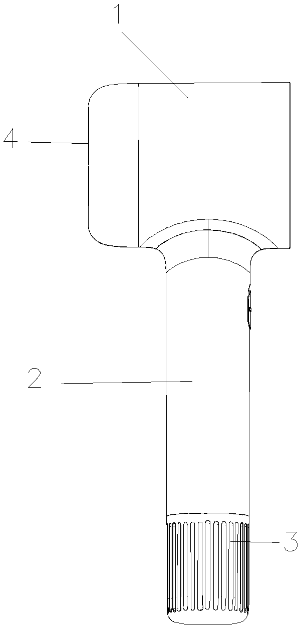
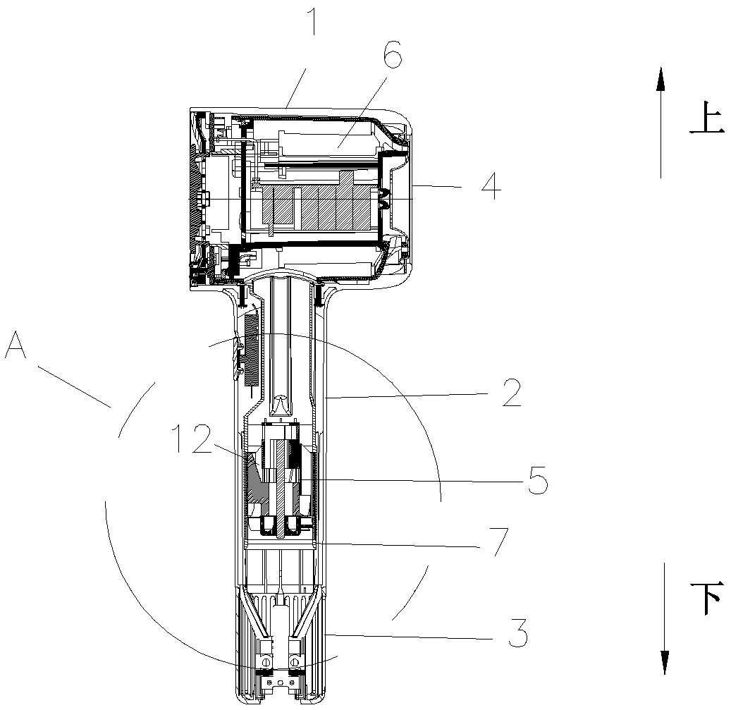
[0061] Such as Figures 1 to 11 As shown, a high-speed hair dryer includes a housing 1, a handle assembly 2 connected to the housing 1, an air inlet 3, an air outlet 4, a fan unit 5 for sucking air from the air inlet 3 into the inside of the hair dryer, and a fan unit 5 for The heating unit 6 for heating the airflow, the fan unit 5 includes a fan blade 502 and a motor 501 for driving the fan blade 502 to rotate, the motor 501 includes a stator assembly 15 and a rotor assembly 16, wherein the motor 501 also includes A bracket for supporting the rotor assembly 16 and the stator assembly 15; the rotor assembly 16 is connected to the fan blade 502 and drives the fan blade 502 to rotate; the bracket includes a first cylinder 8 for supporting the rotor assembly 16 and a housing The second cylinder 9 of the fan blade 502; the first cylinder 8 is arranged on one side of the second cylinder 9 and is connected with the second cylinder 9 through the connecting blade 10; the hair dryer al...

Embodiment 2

[0082] The difference between this embodiment and Embodiment 1 is that, if Figure 12 , 13 As shown, the second cylindrical body 9 includes an air inlet side 13 and an air outlet side 14 , and the first cylindrical body 8 is disposed on the air inlet side 13 of the second cylindrical body 9 .

[0083] The motor 501 can be arranged in the handle assembly 2. At this time, the air inlet 3 is arranged on the handle assembly 2, and the motor 501 is arranged above the air inlet 3. The axis of the motor 501 is the same as that of the handle assembly 2, and the air inlet side 13 is closer to The air inlet 3, when the fan blade 502 rotates, the air flow enters the second cylinder 9 from the air inlet 3, the air inlet 3 is located below the air inlet side 13 of the second cylinder 9, and the first cylinder 8 is located in the second cylinder The motor 501 can also be arranged in the housing 1, the air inlet 3 is arranged at the rear end of the housing 1, the axis of the motor 501 is th...

Embodiment 3

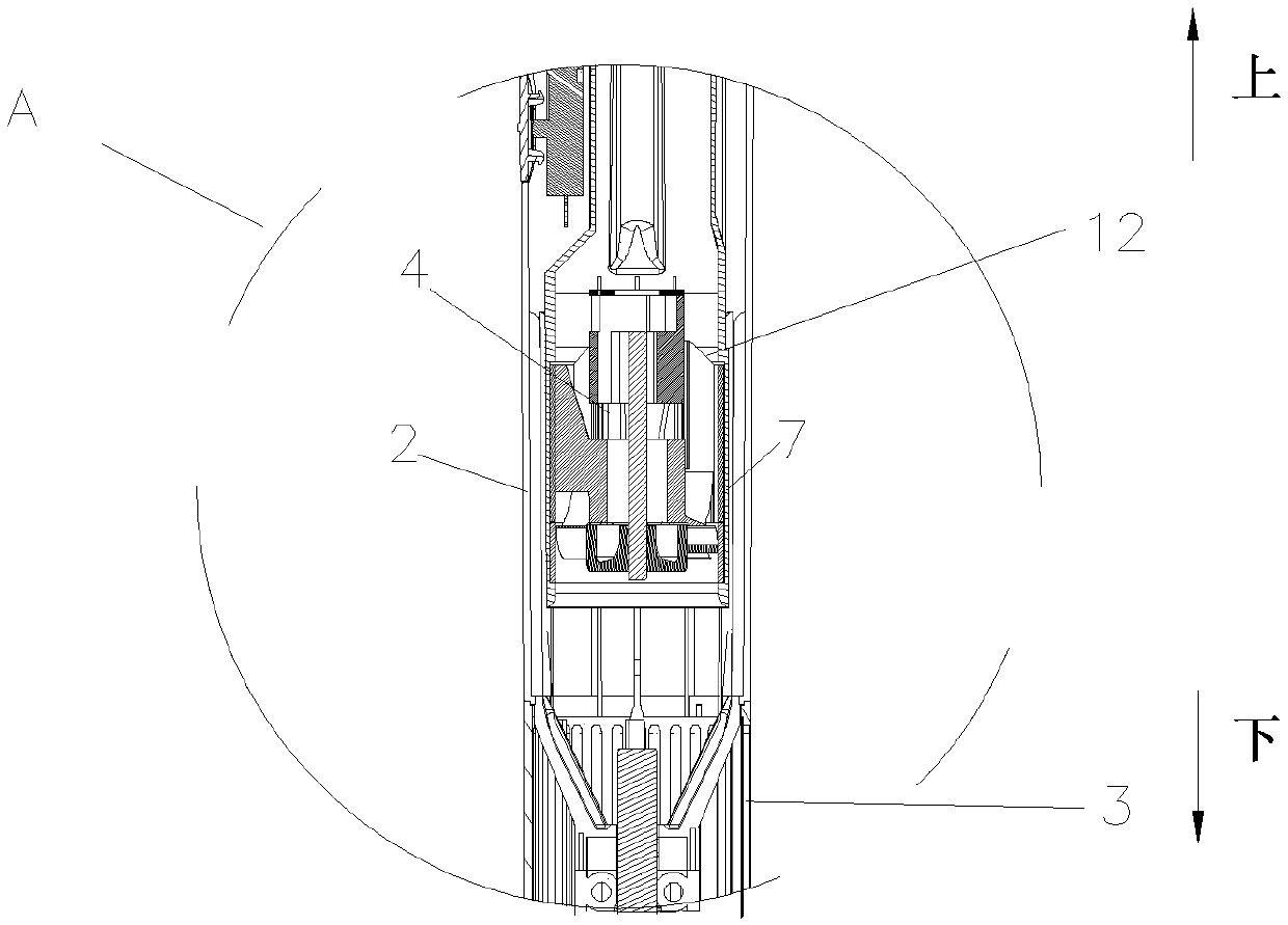
[0088] The difference between this embodiment and any of the above embodiments is that, if Figures 14 to 16 As shown, the hair dryer also includes a third cylinder 11 for fixing the motor 501, the third cylinder 11 and the first cylinder 8 define an air flow channel 12, and the third cylinder 11 is separated from the bracket set up. When the fan blade 502 rotates, the airflow entering the hair dryer from the air inlet 3 first enters the airflow channel 12 and then enters the second cylinder 9; or the airflow entering the hair dryer from the air inlet 3 enters the second cylinder 9 first, Then enter the airflow channel 12.

[0089] Further, the second cylinder 9 includes an air inlet side 13 and an air outlet side 14, and the fan blade 502 rotates so that the airflow enters the second cylinder 9 from the air inlet side 13 and enters the airflow channel through the air outlet side 14 12.

[0090] The third cylinder 11 includes an abutting portion, and the abutting portion ab...


PUM


Abstract

The invention relates to the field of household appliances, and the problems that an electric hair drier is large in size and air volume and air pressure are lost are solved. The present invention especially relates to a high-speed electric hair drier. The high-speed electric hair drier comprises a shell, a handle assembly connected with the shell, an air inlet, an air outlet, a fan unit used forsucking air flow into the electric hair drier from the air inlet, and a heating unit used for heating the air flow. The fan unit comprises fan blades and a motor used for driving the fan blades to rotate, the motor comprises a stator assembly and a rotor assembly, and the motor further comprises a support used for supporting the rotor assembly and the stator assembly. The rotor assembly is connected with the fan blades and drives the fan blades to rotate; the support comprises a first cylinder used for supporting the rotor assembly and a second cylinder used for containing the fan blades. Thefirst cylinder is arranged on one side of the second cylinder and is connected with the second cylinder through a connecting blade; the electric hair drier further comprises an air guide pipe, the second cylinder comprises an air inlet side and an air outlet side, and the fan blades rotate to enable airflow to enter the second cylinder from the air inlet side and enter the air guide pipe from theair outlet side.

Description

technical field [0001] The invention relates to the field of household appliances, in particular to a high-speed hair dryer. Background technique [0002] A hair dryer generally includes a housing assembly, a handle assembly connected to the housing assembly, and a fan unit for sucking air into the interior of the hair dryer, so that the hair dryer can be used to dry or style the hair. The fan unit includes a motor and fan blades driven by the motor to rotate. The speed of the motor affects the air pressure and air volume of the airflow blown out by the hair dryer, which will directly affect the hair blowing efficiency. Most of the motor speeds used in hair dryers on the market are around 20,000 rpm. Due to the influence of the performance of the motor itself, the air volume and air pressure generated by the hair dryer are limited. [0003] Dyson patent CN201621361236.9 discloses a hand-held product using a high-speed motor, and the motor has a relatively high speed, so it ...

Claims


Application Information

Patent Timeline
Patent Type & Authority Applications(China)
IPC IPC(8): A45D20/10A45D20/12
CPCA45D20/10A45D20/12A45D20/124
Inventor 喻金明叶志文肖林张敏
Owner LESHOW ELECTRONICS TECH CO LTD
Learn More