Anti-peeping toilet cubicle

A peeping, toilet technology, applied in building components, door/window accessories, manual mechanisms, etc., can solve the problems of criminals peeping, no anti-peeping device is installed, etc., to reduce the difficulty of cleaning, facilitate cleaning, and ensure privacy and security. Effect

Inactive Publication Date: 2020-08-14
徐超
View PDF19 Cites 0 Cited by
  • Summary
  • Abstract
  • Description
  • Claims
  • Application Information

AI Technical Summary

Problems solved by technology

[0003] The height of the ventilation openings of most public toilets is more than ten centimeters. Therefore, criminals located in adjacent compartments can easily extend mirrors or mobile phones into the compartments on the other side to peep or secretly take pictures. Existing public toilets There is no anti-peeping device, so people can only rely on people's vigilance to protect their own privacy. If people's vigilance is low, it is easy for criminals to achieve the purpose of peeping. For this reason, we propose an anti-peeping toilet cubicle

Method used


Image

  • Anti-peeping toilet cubicle
  • Anti-peeping toilet cubicle
  • Anti-peeping toilet cubicle

Examples


Embodiment 1

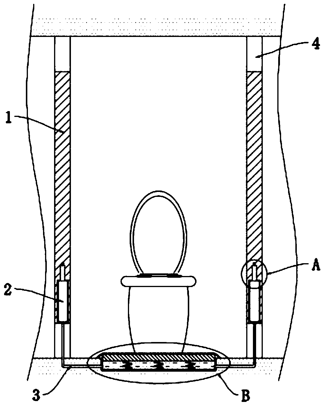
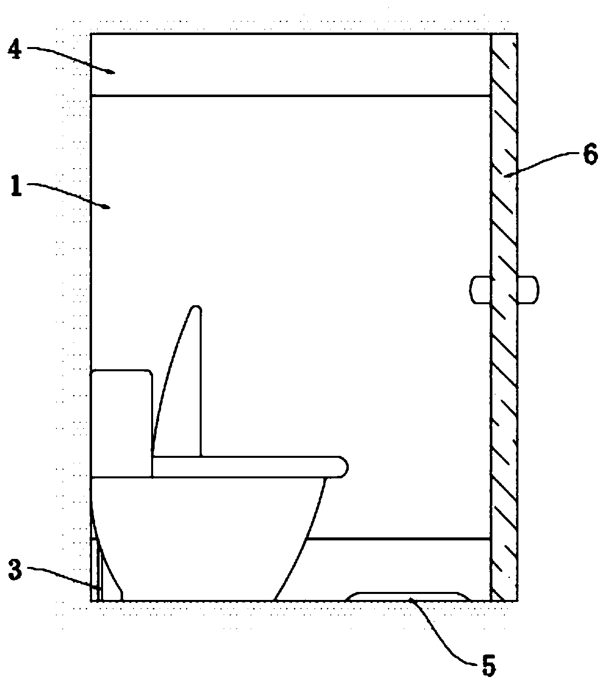
[0030] refer to Figure 1-6 , an anti-peeping type toilet compartment, including two partitions 1 symmetrically installed on the wall, each partition 1 is provided with vents 4 at the upper and lower ends, and the vents 4 can maintain the air circulation in the toilet, To prevent obvious peculiar smell, a door body 6 is also installed between the partition boards. One side of the door body 6 is hinged with one of the partition boards 1, and the other side is movably connected with another partition board 1. Between the two partition boards 1, a There is a stepping device 5, and each partition 1 is provided with an anti-peeping mechanism, and an elbow 3 is connected between each anti-peeping mechanism and the stepping device 5;

[0031] The stepping device 5 includes a U-shaped housing 10 embedded in the ground. A pedal 9 is installed in a sealed and slidable manner in the U-shaped housing 10. A plurality of pedals are symmetrically connected between the lower surface of the pe...

Embodiment 2

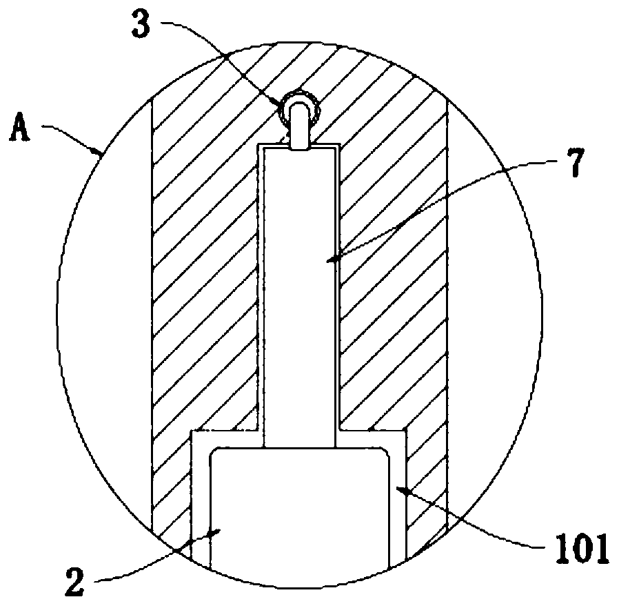
[0040] refer to Figure 7 , The difference between this embodiment and Embodiment 1 is that a plurality of balls 11 are symmetrically installed on the inner wall of the cavity 101, and each ball 11 is against the outer wall of the privacy panel 2, and the balls 11 can limit the privacy of the privacy panel. 2 to prevent the anti-peeping panel 2 from tilting when moving up and down, thereby causing a "stuck" phenomenon.

[0041] When the present embodiment is used, when the anti-peeping plate 2 moves up and down in the placement cavity 101, its outer wall is in contact with the balls 11, because there is rolling friction between the plurality of balls 11 and the anti-peeping plate 2, and the frictional force is small, so The setting of the ball 11 will not affect the normal movement of the privacy panel 2, and there will be no large noise, and the ball 11 can also prevent the privacy panel 2 from slightly tilting, so as to ensure the smooth movement of the privacy panel 2 .


PUM


Abstract

The invention discloses an anti-peeping toilet cubicle. The anti-peeping toilet cubicle comprises two partition plates symmetrically installed on a wall, ventilation openings are formed in the upper ends and the lower ends of the partition plates, a stepping device is arranged between the two partition plates, anti-peeping mechanisms are arranged in the partition plates, bent pipes are arranged between the anti-peeping mechanisms and the stepping device in a communicating mode, the stepping device comprises a U-shaped shell embedded in the ground, a pedal is slidably installed in the U-shapedshell in a sealing mode, and a plurality of return springs are symmetrically connected between the lower surface of the pedal and the inner bottom wall of the U-shaped shell. The anti-peeping toilet cubicle is simple in structure and can automatically block the ventilation openings in the lower parts of the partition plates with anti-peeping plates after people enter the toilet cubicle so as to prevent people with bad intentions from peeping. When people leave the toilet cubicle, the anti-peeping plates can automatically retract to enable the ventilation openings to be in an open state to ensure the normal circulation of air in the cubicle.

Description

technical field [0001] The invention relates to the technical field of construction, in particular to an anti-peeping type toilet cubicle. Background technique [0002] In order to make the maximum use of the space in the public toilet, the compartments in the common public toilet are mostly arranged side by side, and the upper and lower sides of the partition are provided with vents to ensure the circulation of the air in the toilet. [0003] The height of the ventilation openings of most public toilets is more than ten centimeters. Therefore, criminals located in the adjacent compartment can easily extend the mirror or mobile phone into the compartment on the other side to peep or secretly take pictures. The existing public toilets There is no anti-peeping device, so people can only rely on people's vigilance to protect their own privacy. If people's vigilance is low, it is easy for criminals to achieve the purpose of peeping. For this reason, we propose an anti-peeping t...

Claims


Application Information

Patent Timeline
Patent Type & Authority Applications(China)
IPC IPC(8): E05F13/00E05F11/36E04H1/12E04B2/82
CPCE04B2/82E04H1/1216E05F11/36E05F13/00E05Y2900/112E05Y2900/142
Inventor 徐超耿辉
Owner 徐超
Why Eureka
Try Eureka