High-precision automatic viscometer sample inlet unit and viscometer automatic sample injector

A viscometer and sampling port technology, which is applied in the field of liquid sampling equipment, can solve problems such as low precision, influence on use effect, and increase in instrument cost, and achieve the effect of improving the precision of sampling

Pending Publication Date: 2020-08-14
河南阿尔法科学仪器有限公司
View PDF0 Cites 1 Cited by
  • Summary
  • Abstract
  • Description
  • Claims
  • Application Information

AI Technical Summary

Problems solved by technology

[0002] At present, most of the needle-type automatic sampling systems use the injection port of the chromatographic instrument as the sample injection device. When sampling, because the injection needle and the injection port cannot be directly connected, the method of quantitative pump injection is basically used for injection. However, due to the limitations of the quantitative pump itself, the use of quantitative pump injection often results in low precision and low standard deviation. In large cases, it will have a certain impact on the use effect, especially when the sampling accuracy is high, the use of ordinary quantitative pump sampling cannot meet the sampling requirements, and if the high-precision quantitative pump is purchased, the instrument However, the cost has increased significantly, so how to realize the cooperation between the existing needle-type automatic sampling system and the injection port of the viscosity tester is an urgent problem to be solved
[0003] Most of the existing viscosity testers use manual sampling methods, some of them use quantitative pump sampling, and the sampling steps do not fully meet the requirements of the national standard. There is no needle-type automatic sampling device in the market

Method used


Image

  • High-precision automatic viscometer sample inlet unit and viscometer automatic sample injector
  • High-precision automatic viscometer sample inlet unit and viscometer automatic sample injector

Examples


Embodiment 2

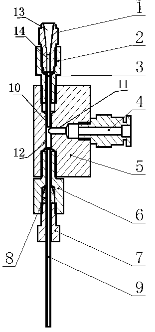
[0029] Sealing Example 2 differs from Example 1 in that the other end of the solvent pipe 3 is also provided with an extension ear along the circumference, and the extension ear is also perpendicular to the solvent pipe 3 axis, and the extension ear provided at one end of the solvent pipe 3 passes through the The cylinder body 1 presses the extension ear so that the upper end of the solvent pipe 3 is sealed with the first screw 2, and the extension ear provided at the other end of the solvent pipe 3 presses the extension ear through the first screw 2 to make the lower end of the solvent pipe 3 contact the first interface 10 Sealed settings. Under the condition that the length of the solvent tube is the same as the length of the through hole of the first screw, by setting an extension ear at the other end of the solvent tube 3, it is possible to ensure that the sample discharged from the injection needle can flow into the injection port of the instrument. , to prevent the sampl...


PUM


Abstract

The invention discloses a high-precision automatic viscometer sample inlet unit and an automatic viscometer sample injector. The high-precision automatic viscometer sample inlet unit comprises a sample injection needle guide unit, a three-way joint, a gas inlet screw and a sample injection pipe. An output port of the sample injection needle guide unit and a first interface of the three-way joint are arranged in a sealed manner, and the gas inlet screw and a second interface of the three-way joint are arranged in a sealed manner; and one end of the sample injection pipe is sealed with a third interface of the three-way joint, and the other end of the sample injection pipe is communicated with a sample injection port of a chromatographic instrument. According to the invention, the high-precision liquid sample inlet device matching the sample injection needle is arranged on a sample injection station; the high-precision liquid sample inlet device has the advantages that the sample injection requirement of the sample injection needle can be met; therefore, after each time of sample injection is completed, the device blows air to the device, so that residual samples can enter instrumentequipment, the cleanness of a sample injection pipeline is ensured, and the sample injection precision is greatly improved while a problem that an existing automatic sample injector does not match aninterface of sample injection equipment is solved.

Description

technical field [0001] The invention relates to the technical field of liquid sampling equipment, in particular to a high-precision automatic viscometer sampling port unit and a viscometer automatic sample injector. Background technique [0002] At present, most of the needle-type automatic sampling systems use the injection port of the chromatographic instrument as the sample injection device. When sampling, because the injection needle and the injection port cannot be directly connected, the method of quantitative pump injection is basically used for injection. However, due to the limitations of the quantitative pump itself, the use of quantitative pump injection often results in low precision and low standard deviation. In large cases, it will have a certain impact on the use effect, especially when the sampling accuracy is high, the use of ordinary quantitative pump sampling cannot meet the sampling requirements, and if the high-precision quantitative pump is purchased, ...

Claims


Application Information

Patent Timeline
Patent Type & Authority Applications(China)
IPC IPC(8): G01N11/00G01N35/10
CPCG01N11/00G01N35/10G01N35/1009
Inventor 贺东霞路辉丽
Owner 河南阿尔法科学仪器有限公司
Why Eureka
Try Eureka