Sampling device for vacuum coating sample and sampling method thereof

A sampling device and vacuum coating technology, which is applied in the direction of sampling device, vacuum evaporation coating, sputtering coating, etc., can solve the problem of unstable storage of vacuum coating samples, and achieve the effect of fastening samples and improving practicability

Pending Publication Date: 2022-06-03
RES INST OF PHYSICAL & CHEM ENG OF NUCLEAR IND
View PDF0 Cites 0 Cited by
  • Summary
  • Abstract
  • Description
  • Claims
  • Application Information

AI Technical Summary

Problems solved by technology

[0004] The purpose of the present invention is to provide a sampling device for vacuum coating samples to solve the problem of unstable storage of vacuum coating samples on the sampling device

Method used


Image

  • Sampling device for vacuum coating sample and sampling method thereof
  • Sampling device for vacuum coating sample and sampling method thereof
  • Sampling device for vacuum coating sample and sampling method thereof

Examples


Embodiment 1

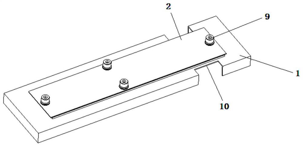
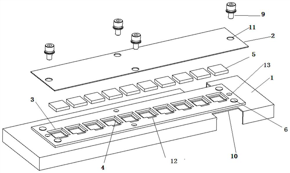
[0039] A sampling device for vacuum coating samples, comprising a sampling device base 1 and a sampling device cover plate 2, the sampling device base 1 is provided with one or more sampling chip mounting grooves 3, and the sampling chip mounting grooves 3 are up and down. An open groove, a boss 4 is provided in the sample chip installation groove 3 to receive the sample chip 5, and the sample device cover plate 2 is detachably assembled on the sample device base 1 to cover all the sample chip installation grooves 3.

[0040] Preferably, there are a plurality of the sampling piece installation slots 3 , which are evenly distributed on the base 1 of the sampling device in a matrix.

[0041] The sampling method of the sampling device comprises the following steps:

[0042] In step 1, firstly, the vacuum coating samples 5 are loaded into the sample installation groove 3 in sequence, and then the sampling device cover plate 2 is installed on the top of the sampling device base 1 ...

Embodiment 2

[0047] The base 1 of the sampling device can either adopt an integrally formed structure, or can adopt the following split structure:

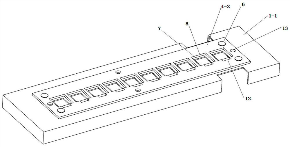
[0048] Preferably, the sampling device base 1 is formed by fixedly connecting a lower base plate 1-1 and an upper base plate 1-2, and the lower base plate 1-1 is provided with a plurality of lower through holes 7. The upper base plate 1-2 is provided with one or more upper through holes 8, the lower through holes 7 and the upper through holes 8 are correspondingly arranged one by one, and the size of the lower through holes 7 is smaller than that of the upper through holes 8. The size of the hole 8 , each corresponding upper through hole 8 and lower through hole 7 correspondingly forms one of the sample chip mounting grooves 3 . The base of the sampling device is formed by CNC machining and riveting.

[0049] Further, the lower base plate 1-1 includes an upper plane plate and a side support plate fixed on the edge of the upper plane plate, wh...

Embodiment 3

[0053] The detachable connection method of the sampling device base 1 and the sampling device cover plate 2 can be in any manner, such as snap connection, adsorption connection, etc., preferably the following connection is fastened by bolts.

[0054] Preferably, the sampling device base 1 is provided with threaded holes, the sampling device cover plate 2 is provided with through holes 11 , the through holes and the threaded holes are arranged in a one-to-one correspondence, and the screw fasteners 9 pass through The sampling device cover plate 2 is fastened on the sampling device base 1 through the through holes 11 and the threaded holes 13, and the disassembly is realized by the cooperation of the screws and the threaded holes, and the disassembly is convenient and quick.

[0055] Preferably, the sampling device base 1 is provided with two symmetrically arranged gaps 10, and the gaps are gaps 10 for the manipulator to grasp, which is convenient for the manipulator to grasp the s...


PUM


Abstract

The invention discloses a sampling device for a vacuum coating sample and a sampling method thereof.The sampling device comprises a sampling device base and a sampling device cover plate, the sampling device base is provided with one or more sampling piece installation grooves, the sampling piece installation grooves are grooves with the upper portions and the lower portions open, and the sampling piece installation grooves are communicated with the sampling device base. Bosses are arranged in the sampling piece mounting grooves to bear sample pieces, and the sampling device cover plate is detachably assembled on the sampling device base to cover all the sampling piece mounting grooves. In the transferring and mounting process, the sample is fastened, and the risk that the sample falls off and is lost is avoided.

Description

technical field [0001] The invention relates to the technical field of vacuum coating, in particular to a sampling device for vacuum coating samples and a sampling method thereof. Background technique [0002] The vacuum electron beam evaporation coating is to act on the crucible molten pool through the deflection of the electron beam. The metal in the molten pool is heated and melted and forms atomic vapor that leaves the liquid surface of the metal molten pool. The evaporated atomic vapor acts on the substrate to form a coating. Usually, according to the length of the action time, the temperature of substrate film formation and other factors, the quality of the formed coating is often different. In some specific occasions, due to the influence of the physical and chemical properties of the material itself, it is not suitable for people to perform close contact operations, and can only operate through intermediate means, such as manipulators, glove boxes, etc. This operati...

Claims


Application Information

Patent Timeline
Patent Type & Authority Applications(China)
IPC IPC(8): G01N1/04C23C14/30
CPCG01N1/04C23C14/30Y02P10/25
Inventor 闫超吕绪明罗立平
Owner RES INST OF PHYSICAL & CHEM ENG OF NUCLEAR IND
Why Eureka
Try Eureka