Particle rendering method, device and apparatus

A particle and attribute technology, applied in the field of particle rendering methods, devices and equipment, can solve the problems of separate code programming and poor design reusability, and achieve the effect of improving rendering efficiency and reducing storage costs

Active Publication Date: 2020-08-14
ALIPAY (HANGZHOU) INFORMATION TECH CO LTD
View PDF5 Cites 7 Cited by
  • Summary
  • Abstract
  • Description
  • Claims
  • Application Information

AI Technical Summary

Problems solved by technology

[0004] This manual provides a particle rendering method, device, and equipment to solve the problem of poor design

Method used


Image

  • Particle rendering method, device and apparatus
  • Particle rendering method, device and apparatus
  • Particle rendering method, device and apparatus

Examples


Embodiment 1

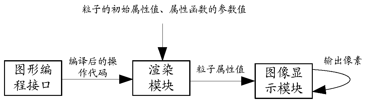
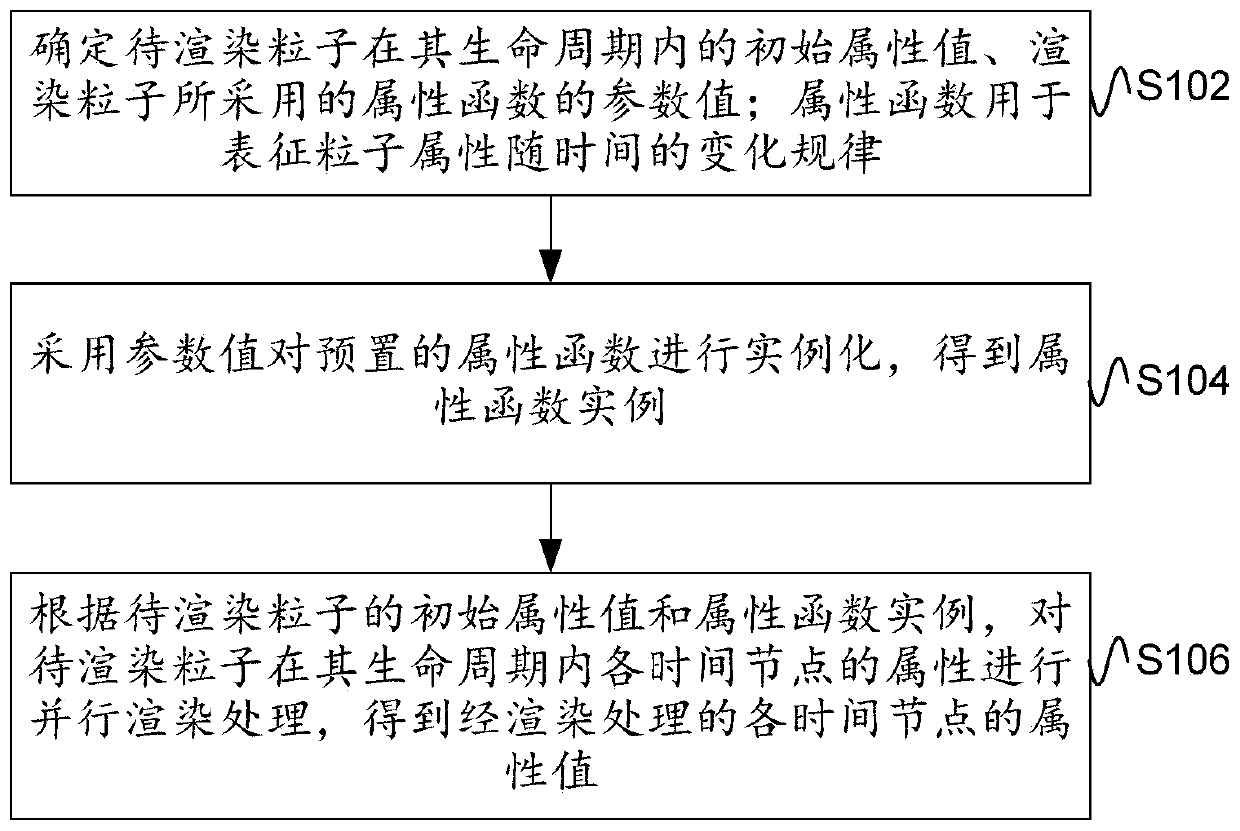
[0041] Based on the above application scenario architecture, figure 2 Schematic flowchart of the particle rendering method provided by the embodiment of this specification Figure 1 , figure 2 methods in figure 1 The rendering module in the execution, such as figure 2 As shown, the method includes the following steps:

[0042] Step S102, determine the initial attribute value of the particle to be rendered within its life cycle, and the parameter value of the attribute function used to render the particle; the attribute function is used to represent the change rule of the particle attribute over time.

[0043] Among them, the particles to be rendered can be a particle system composed of a large number of particles. A particle system can be regarded as a collection containing a large number of similarly drawn particles. The particles in the collection can be uploaded to the rendering module in batches for rendering. Each particle corresponds to its own life cycle, and the...

Embodiment 2

[0073] This embodiment is on the basis of embodiment one, to figure 2 The particle rendering methods shown are extended and supplemented.

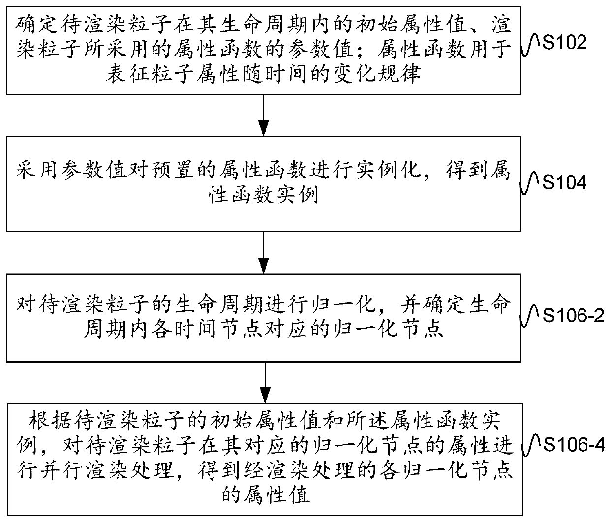
[0074] image 3 Schematic flowchart of the particle rendering method provided by the embodiment of this description Figure II ,Such as image 3 As shown, the step S106 may include:

[0075] S106-2. Normalize the life cycle of the particle to be rendered, and determine the normalization node corresponding to each time node in the life cycle.

[0076] Specifically, the life cycle of a particle represents the existence time of the particle, and normalizing the life cycle may be normalizing life cycles of different durations into a unified interval, for example, normalizing into the interval [0, 1]. For example, the total life cycle of a particle is 3 seconds, and when the pixel animation progresses to 1.5 seconds, the normalized life cycle of the particle is 1.5s / 3s=0.5. When the particle life cycle > 0, the particle starts to calculat...

Embodiment 3

[0089] corresponding to the above Figure 2 to Figure 3 The described particle rendering method is based on the same technical idea, and the embodiment of this specification also provides a particle rendering device. Figure 4 A schematic diagram of the module composition of the particle rendering device provided by the embodiment of this specification, which is used to execute Figure 2 to Figure 3 Describes particle rendering methods such as Figure 4 As shown, the device includes:

[0090] The information determination module 201 is used to determine the initial attribute value of the particle to be rendered within its life cycle, and the parameter value of the attribute function used to render the particle; the attribute function is used to characterize the change rule of the particle attribute over time;

[0091] The instance processing module 202 instantiates the preset attribute function by using the parameter value to obtain the attribute function instance;

[0092]...


PUM


Abstract

The embodiment of the invention provides a particle rendering method, device and apparatus and the method comprises the steps: determining an initial attribute value of a to-be-rendered particle in alife cycle of the to-be-rendered particle, and a parameter value of an attribute function employed by the rendered particle; wherein the attribute function is used for representing a change rule of particle attributes along with time; instantiating the preset attribute function by adopting the parameter value to obtain an attribute function instance; obtaining an initial attribute value of the to-be-rendered particle according to the initial attribute value of the to-be-rendered particle and the attribute function instance; and performing parallel rendering processing on the attribute of eachtime node of the to-be-rendered particle in the life cycle of the to-be-rendered particle to obtain an attribute value of each time node after rendering processing, thereby solving the problems that in the prior art, when particle rendering is performed each time, a code program needs to be written independently, and the design reusability is relatively poor.

Description

technical field [0001] This document relates to the field of computer technology, in particular to a particle rendering method, device and equipment. Background technique [0002] Particle effects are production modules developed by various 3D software to simulate real effects such as water, fire, fog, and gas. The principle is to combine countless single particles to make them appear in a fixed shape. Control its overall or individual movement to simulate real effects. [0003] Currently, there is no general way to render particle effects on the web. The code needs to be designed separately every time special effect rendering is performed, which is not conducive to code accumulation and design reuse. Contents of the invention [0004] This specification provides a particle rendering method, device and equipment, which are used to solve the problem of poor design reusability due to the need to write a separate code program each time particle rendering is performed in the...

Claims


Application Information

Patent Timeline
IPC IPC(8): G06T15/00G06T1/20
CPCG06T15/005G06T1/20G06T2210/56
Inventor 曾柏然
Owner ALIPAY (HANGZHOU) INFORMATION TECH CO LTD
Why Eureka
Try Eureka