Antenna tuner

An antenna tuner and antenna rod technology, applied in the field of antenna tuners, can solve the problems of antenna mismatch, reduce radiated power, cannot frequently change the antenna structure, etc., and achieve the effect of efficient matching

Active Publication Date: 2020-08-14
吉林吉大通信设计院股份有限公司
View PDF10 Cites 1 Cited by
  • Summary
  • Abstract
  • Description
  • Claims
  • Application Information

AI Technical Summary

Problems solved by technology

[0004] Aiming at the deficiencies in the prior art, the purpose of the present invention is to provide an antenna tuner to solve the problem that the existing antenna tuner is sometimes installed in a relatively high altitude

Method used


Image

  • Antenna tuner
  • Antenna tuner
  • Antenna tuner

Examples


no. 1 example

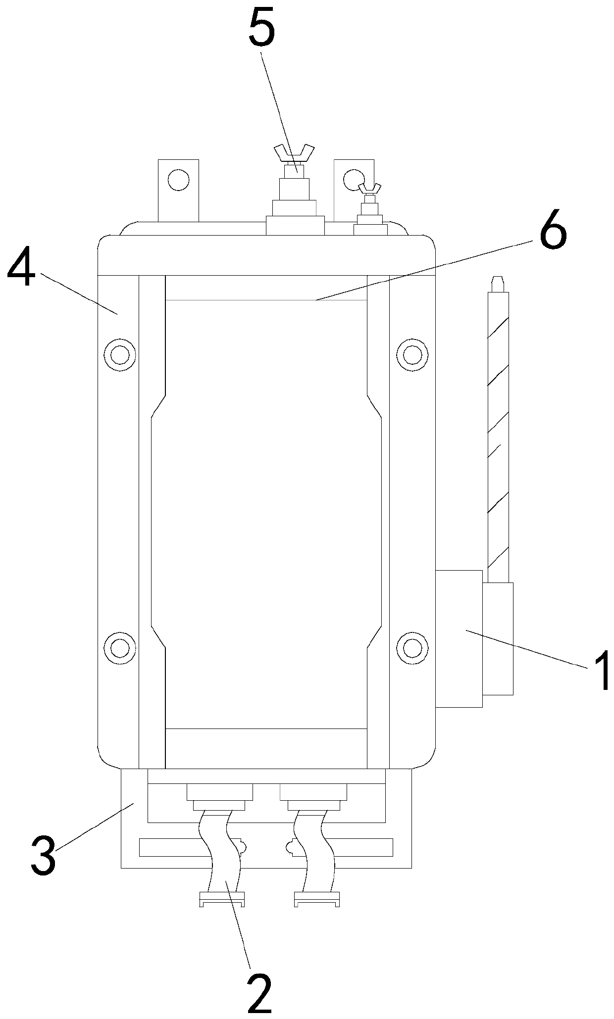
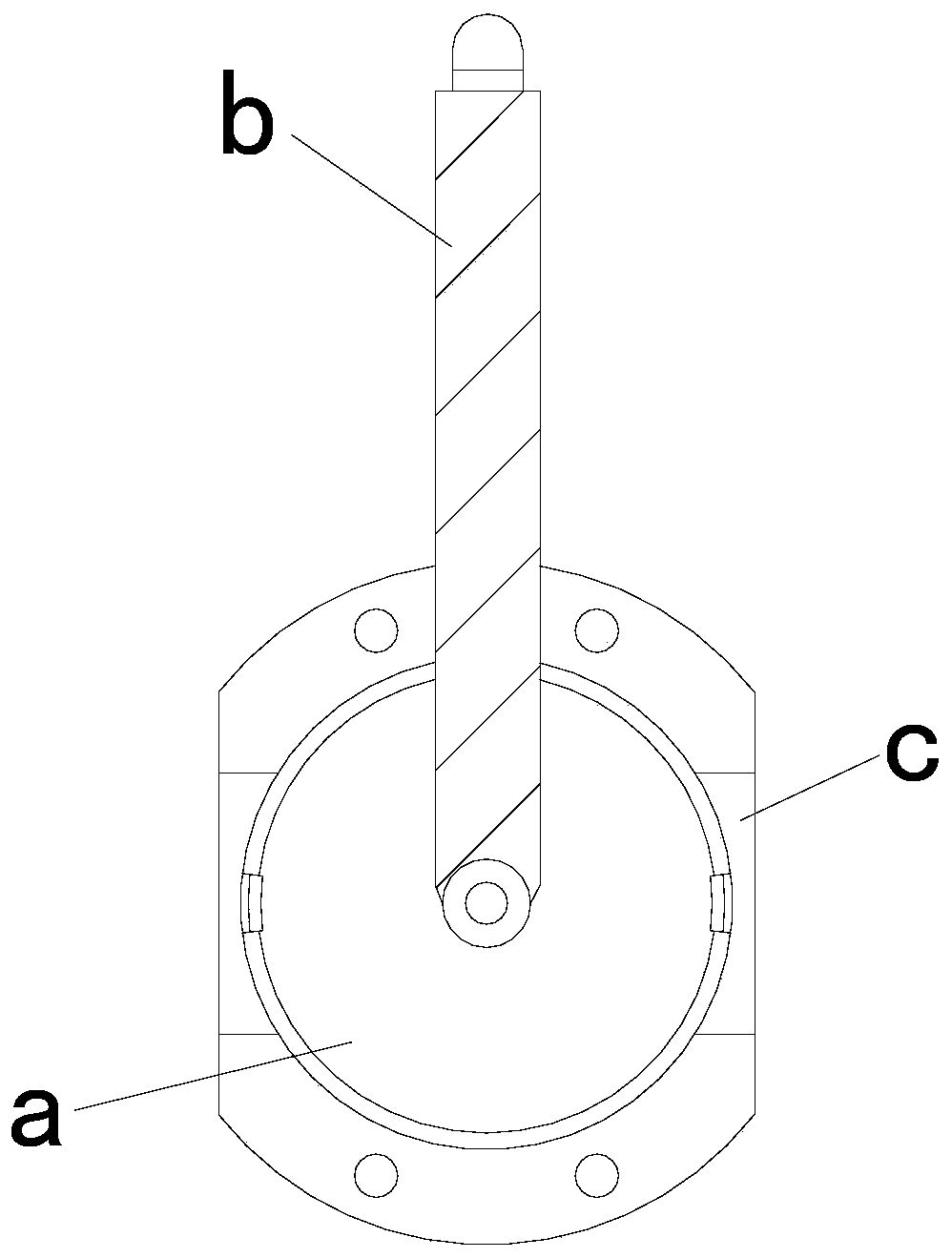
[0025] see Figure 1-Figure 3 , the present invention provides a technical solution for an antenna tuner: its structure includes: an antenna device 1, a terminal 2, a fixed piece 3, a protective case 4, a signal adjustment terminal 5, and a circuit tank 6, and the circuit tank 6 is installed in The inner side of the protective case 4 is locked with the protective case 4, the upper end of the circuit tank 6 is provided with a signal adjustment terminal 5, the signal adjustment terminal 5 is electrically connected with the circuit tank 6, and the lower end of the circuit tank 6 is provided with a wiring Terminal 2, the terminal 2 is fastened to the circuit tank 6, the side of the circuit tank 6 is provided with an antenna device 1, the antenna device 1 is electrically connected to the circuit tank 6, and the side of the protective shell 4 is provided There is a fixed piece 3 and is locked with the fixed piece 3. The antenna device 1 includes a coupler device a, an antenna rod b,...

no. 2 example

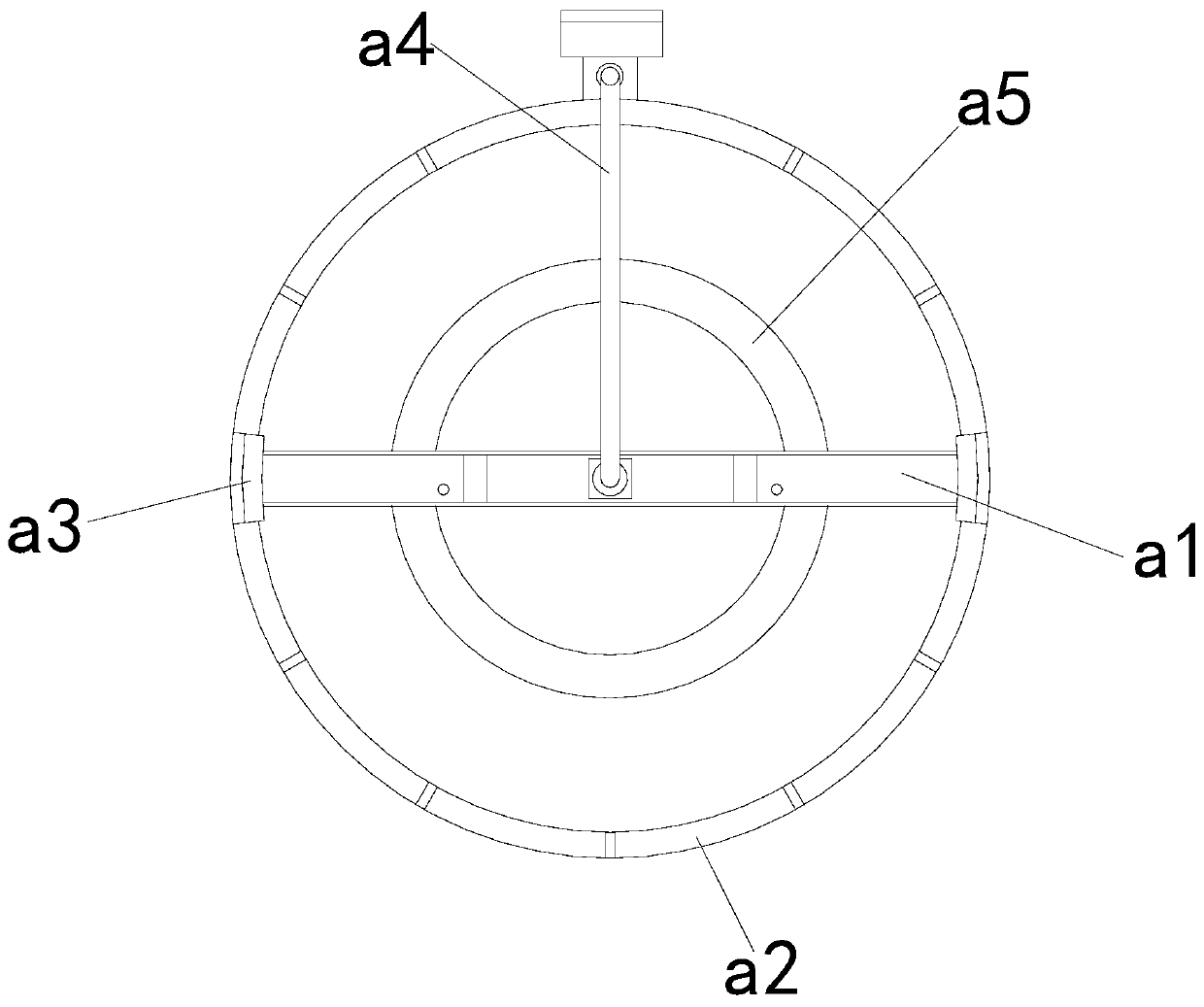
[0029] see Figure 4-Figure 5 , the present invention provides a technical solution for an antenna tuner: its structure includes: the frequency multiplier a1 includes a loading tube a11, a signal auxiliary device a12, a spring plate a13, and a connecting frame a14, and the signal auxiliary device a12 is arranged on the loading The inner side of the pipe a11 is in clearance fit with the loading pipe a11, the inner side of the loading pipe a11 is provided with a connecting frame a14, the connecting frame a14 is movably connected with the loading pipe a11, and the inner side of the connecting frame a14 is provided with a spring plate a13, The spring plate a13 is fastened to the connection frame a14.

[0030] The signal auxiliary device a12 includes an inner core tube a121, a signal bar a122, a laying slot a123, and a movable seat a124. side and fastened with the movable seat a124, the inner core pipe a121 runs through the inside of the movable seat a124, the inner core pipe a121...


PUM


Abstract

The invention discloses an antenna tuner which structurally comprises an antenna device, a wiring terminal, a fixed sheet, a protective shell, a signal adjusting terminal and a circuit groove box. When a device is used, a frequency raiser mechanism is arranged. In the working process of the antenna tuner, for a surrounding-variable environment, when the frequency of a transmitter is changed, the impedance between the transmitter and the antenna is not matched, the radiation power is reduced, the operation is troublesome, fine adjustment is difficult to perform, the frequent mismatch of the antenna is caused, and the structure of the antenna cannot be frequently changed, the above problems are solved by the invention, the equipment is matched with a bearing frame through a linkage swing rod; the limitation of a traditional antenna fixing mode is broken through, meanwhile, an auxiliary supporting scheme is provided for signals of an antenna mast, the coverage points of the frequency raiser can be flexibly increased through signal strips, the impedance between the transmitter and the antenna is effectively adjusted, and the signal feedback is efficiently matched and more convenient.

Description

technical field [0001] The invention is an antenna tuner and belongs to the field of tuner equipment. Background technique [0002] The antenna tuner is an impedance matching network connecting the transmitter and the antenna. It can match the impedance between the transmitter and the antenna, so that the antenna has the maximum radiated power at any frequency. It is widely used in ground, vehicle, ship Carried and aeronautical shortwave radio. [0003] The prior art has the following deficiencies: during the working process of the antenna tuner, because it is sometimes installed in a relatively high altitude environment, facing the changing environment around, when the frequency of the transmitter changes, the distance between the transmitter and the antenna If the impedance does not match between them, the radiation power will be reduced. It is very troublesome to operate, and it is difficult to make fine adjustments, resulting in frequent mismatching of the antenna and t...

Claims


Application Information

Patent Timeline
IPC IPC(8): H01Q1/50H01Q1/12H01Q5/335H04B1/03
CPCH01Q1/12H01Q1/50H04B1/03H01Q5/335
Inventor 罗斌
Owner 吉林吉大通信设计院股份有限公司
Why Eureka
Try Eureka