Centrifuge rotor

A technology of centrifuge rotor and rotation axis, which is applied in the direction of centrifuge, etc., to achieve the effect of increasing the service life

Active Publication Date: 2020-08-14
埃佩多夫欧洲股份公司
View PDF14 Cites 0 Cited by
  • Summary
  • Abstract
  • Description
  • Claims
  • Application Information

AI Technical Summary

Problems solved by technology

However, this last step still requires two hands

Method used


Image

  • Centrifuge rotor
  • Centrifuge rotor
  • Centrifuge rotor

Examples


Embodiment Construction

[0046] Figure 1 to Figure 8 are various views of a centrifuge rotor 10 and its components in accordance with the present invention.

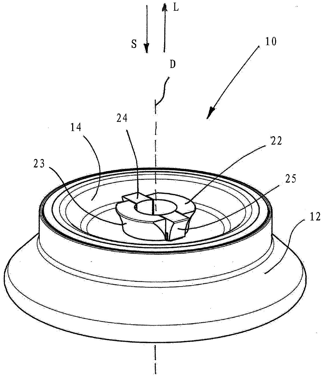
[0047] It is clear that the centrifuge rotor 10 is as rotationally symmetrical as possible and comprises a lower part 12 and a cover 14, wherein the cover 14 is placed on the lower part 12 in a closing direction S parallel to the axis of rotation D and can be moved parallel to the The axis of rotation D is removed in the disassembly direction L.

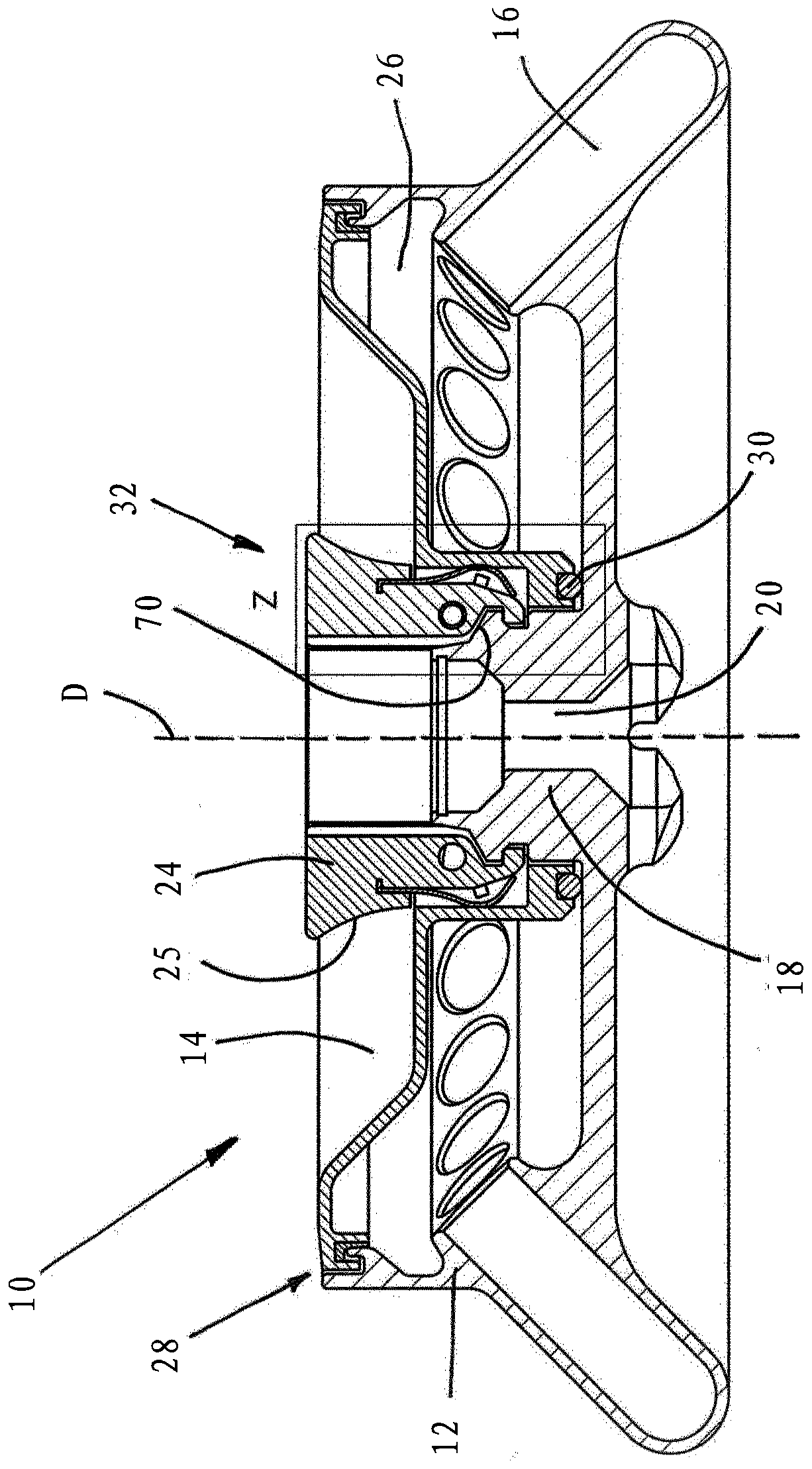
[0048] Lower portion 12 includes a series of evenly spaced holes or compartments 16 for receiving sample vessels (not shown), for example in the form of test tubes. Centrally arranged in the lower part 12 is a hub 18 comprising a bore 20 capable of receiving a drive shaft of a laboratory centrifuge (neither shown) by means of which the centrifuge rotor 10 can be driven. A carrying handle 22 including an undercut 23 is provided for grasping, the carrying handle 22 is formed on the hub 18 so as to pro...


PUM


Abstract

The invention relates to a centrifuge rotor (10), in which the closure (32) between the lower part (12) of the centrifuge rotor (10) and the cover (14) has been improved such that true one-handed operability is enabled. In particular, the closure (32) can be closed and released again with just one hand. The closure (32) is constructionally simple and also more economical to produce.

Description

technical field [0001] The invention relates to a centrifuge rotor according to the preamble of claim 1 . Background technique [0002] Centrifuge rotors are used in centrifuges, especially laboratory centrifuges, to separate components of a sample being centrifuged therein using inertia. In this process, higher rotational speeds are used to achieve high separation rates. In this case, a laboratory centrifuge is a centrifuge whose rotor runs at a speed of preferably at least 3,000 revolutions per minute, preferably at least 10,000 revolutions, especially at least 15,000 revolutions, and is usually placed on a bench. In order to be able to place the centrifuges on a bench, they in particular have a form factor of less than 1 m x 1 m x 1 m, ie their installation space is limited. Preferably, the appliance depth is limited here to a maximum of 70 cm. [0003] The sample is usually centrifuged at a certain temperature. For example, such samples containing proteins and organi...

Claims


Application Information

Patent Timeline
Patent Type & Authority Applications(China)
IPC IPC(8): B04B5/04B04B7/02B04B7/08
CPCB04B5/0414B04B7/02B04B7/08B04B2007/025B04B5/04B04B9/00B04B2009/085
Inventor S·库纳特C·克诺斯佩
Owner 埃佩多夫欧洲股份公司
Why Eureka
Try Eureka