A Hydraulically Driven Constant Pressure Constant Displacement Friction Stir Welding Spindle Unit

A technology of friction stir welding and constant pressure, which is applied in welding equipment, non-electric welding equipment, metal processing equipment, etc.

Active Publication Date: 2021-11-30
CAPITAL AEROSPACE MACHINERY +1
View PDF0 Cites 0 Cited by
  • Summary
  • Abstract
  • Description
  • Claims
  • Application Information

AI Technical Summary

Problems solved by technology

[0006] The technical solution of the present invention is: a hydraulically driven constant pressure and constant displacement friction stir welding spindle unit, which is used to solve the problem of constant pressure and constant displacement control in the heavy-duty friction stir welding process. The friction stir welding spindle unit is installed on the gantry Inside the fork-shaped structural member at the end of the main frame ram, the longitudinal seam of the box bottom is welded along the welding track through the main frame of the gantry and the double fork; including:

Method used


Image

  • A Hydraulically Driven Constant Pressure Constant Displacement Friction Stir Welding Spindle Unit
  • A Hydraulically Driven Constant Pressure Constant Displacement Friction Stir Welding Spindle Unit
  • A Hydraulically Driven Constant Pressure Constant Displacement Friction Stir Welding Spindle Unit

Examples


Embodiment 1

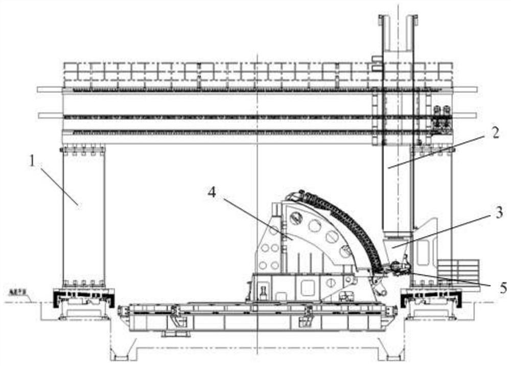
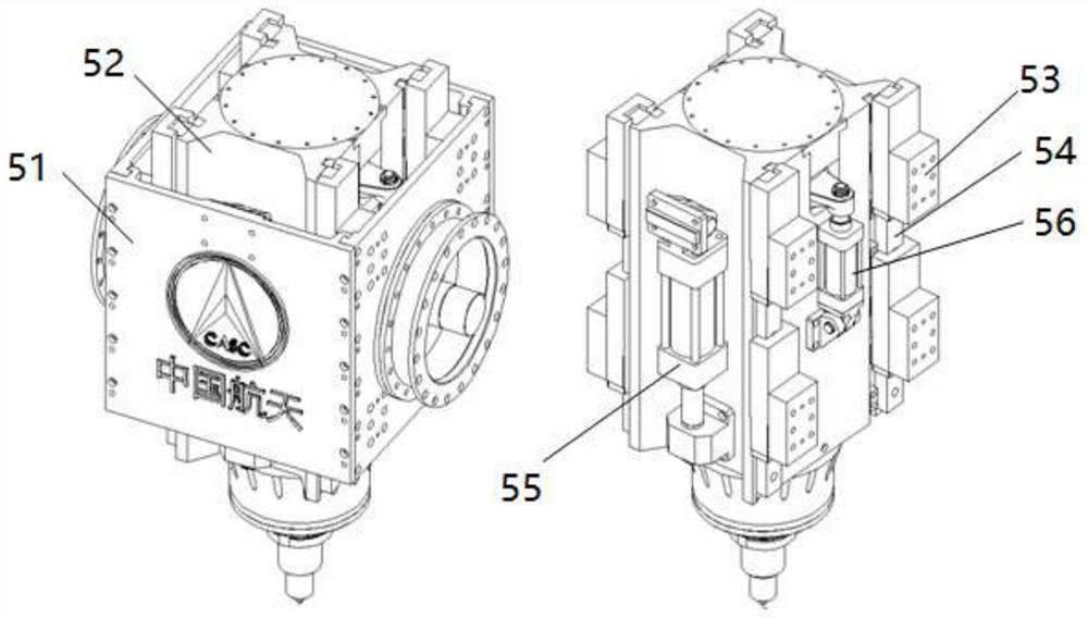
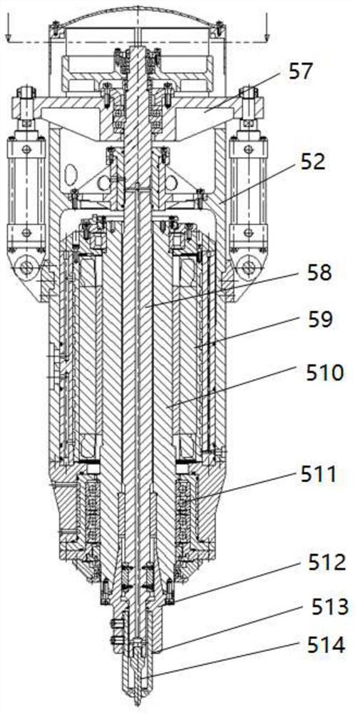
[0029] A hydraulically driven constant pressure and constant displacement friction stir welding spindle unit 5 is used to solve the problem of constant pressure and constant displacement control in the heavy load friction stir welding process, such as figure 1 and figure 2 The friction stir welding spindle unit 5 shown is installed inside the fork-shaped structural member 3 at the end of the ram end of the frame of the gantry main body 1, and completes the welding of the longitudinal seam of the bottom of the box along the welding track through the frame of the gantry main body 1 and the double forks; including: Between the slide box 51 and the main shaft housing 52, two sets of symmetrical shoulders are pressed into the servo cylinder 55 for driving. The tailstock of the servo cylinder body is fixedly connected with the outer slide box 51. 52 is fixedly connected, and the plunger is extended or retracted by controlling the oil cylinder, thereby causing relative movement betw...


PUM


Abstract

The invention discloses a hydraulically driven constant pressure and constant displacement friction stir welding main shaft unit, which is used to solve the problem of constant pressure and constant displacement control in the heavy load friction stir welding process. The friction stir welding main shaft unit is installed on the main frame ram of the gantry Inside the fork-shaped structural part at the end, the longitudinal seam of the bottom of the box is welded along the welding track through the main frame of the gantry and the double fork; including: two sets of symmetrical shoulders are pressed into the servo cylinder between the outer slide box and the main shaft housing. Drive, the tailstock of the servo cylinder body is fixedly connected with the outer slide box, and the plunger of the servo cylinder is fixedly connected with the main shaft housing through the connecting piece. There is relative movement between them, that is, the press-in movement of the shoulder, which is defined as the Z1 axis; the slider is fixedly connected to the outer slider box, and the linear guideway is fixedly connected to the main shaft housing. Four sets of symmetrically arranged sliders and the linear guideway It constitutes the guiding mechanism for the press-in movement of the shoulder; the servo cylinder of the Z1 axis is connected with the high-frequency proportional valve.

Description

technical field [0001] The invention relates to a hydraulically driven constant pressure and constant displacement friction stir welding spindle unit, which can be used to solve the problem of constant pressure and constant displacement control in the process of heavy-duty friction stir welding, and belongs to the development technology of friction stir assembly welding automation equipment for large storage tanks of launch vehicles field. Background technique [0002] With the development of my country's aerospace industry, higher requirements are put forward for the carrying capacity of the launch vehicle, so its structural scale has a significant trend of gradually increasing. Taking the heavy-duty launch vehicle (CZ-9) under research in my country as an example, the maximum diameter of the core-level tank reaches 10m, and the maximum wall thickness of the tank reaches 18-24mm. According to the practical experience of welding and forming tanks of existing models in our f...

Claims


Application Information

Patent Timeline
Patent Type & Authority Patents(China)
IPC IPC(8): B23K20/12B23K20/26
CPCB23K20/1255B23K20/26
Inventor 毕煌圣孙世烜陈雪峰戴钦刘海燕呼啸张新宇郝云飞肖喜龙孔德跃高彦军杜岩峰王志峰毛京伟李世鹏胡改娟杨富伟何凡锋魏瑞刚
Owner CAPITAL AEROSPACE MACHINERY
Why Eureka
Try Eureka