
Fluid sensor

A sensor and fluid technology, applied in the direction of measuring fluid pressure, instruments, measuring devices, etc., can solve the problems of cumbersome installation, heavy workload, limited scope of application, etc.

Pending Publication Date: 2020-08-18
东莞市石桥机电设备有限公司
View PDF0 Cites 0 Cited by
  • Summary
  • Abstract
  • Description
  • Claims
  • Application Information

AI Technical Summary

Problems solved by technology

[0002] At present, there are very few pressure monitoring devices used on the market. The installation is mainly through the way of punching the glue head, and the pressure sensor is embedded in the mechanical structure to contact the fluid to monitor. The installation is cumbersome, the workload is heavy, and the sensor is easy to damage. , the scope of application is limited, and the cost is high. For this reason, a fluid sensor is proposed

Method used


Image

  • Fluid sensor

Examples


Embodiment Construction

[0012] The following will clearly and completely describe the technical solutions in the embodiments of the present invention with reference to the accompanying drawings in the embodiments of the present invention. Obviously, the described embodiments are only some, not all, embodiments of the present invention. Based on the embodiments of the present invention, all other embodiments obtained by persons of ordinary skill in the art without making creative efforts belong to the protection scope of the present invention.

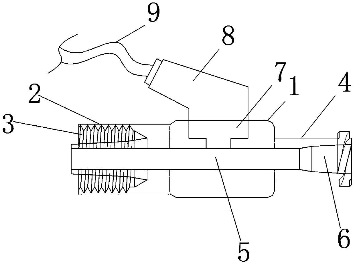
[0013] see figure 1 , in the embodiment of the present invention, the fluid sensor includes a first protective sheath body 1, a third protective sheath body 4 is laterally formed on the right side of the first protective sheath body 1, and the left side of the first protective sheath body 1 A second protective sheath body 2 is laterally formed on the side, and the second protective sheath body 2 and the third protective sheath body 4 respectively communicate w...


PUM


Abstract

The invention discloses a fluid sensor, which comprises a first protective sleeve body, a third protective sleeve body is transversely formed on the right side of the first protective sleeve body, a second protective sleeve body is transversely formed on the left side of the first protective sleeve body, and the second protective sleeve body and the third protective sleeve body communicate with the first protective sleeve body; a Luer taper female head is transversely formed in the second protective sleeve body, and the second protective sleeve body is in through connection with external fluiddischarge equipment through the Luer taper female head; a Luer taper male head is transversely formed in the third protective sleeve body, and the third protective sleeve body is in through connection with external fluid discharge equipment through the Luer taper male head; a fluid channel is transversely formed in the first protective sleeve body in a penetrating mode, penetrates through the second protective sleeve body and the third protective sleeve body and is connected with the Luer taper male head and the Luer taper female head in a penetrating mode.

Description

technical field [0001] The invention relates to the field of pressure detection devices, in particular to a fluid sensor. Background technique [0002] At present, there are very few pressure monitoring devices used on the market. The installation is mainly through the way of punching the glue head, and the pressure sensor is embedded in the mechanical structure to contact the fluid to monitor. The installation is cumbersome, the workload is heavy, and the sensor is easy to damage. , the scope of application is limited, and the cost is high, so a fluid sensor is proposed for this purpose. Contents of the invention [0003] In order to overcome the disadvantages of the above-mentioned situation, the present invention aims to provide a technical solution capable of solving the above-mentioned problems. [0004] The fluid sensor includes a first protective sheath body, a third protective sheath body is laterally formed on the right side of the first protective sheath body, a...

Claims


Application Information

Patent Timeline
Patent Type & Authority Applications(China)
IPC IPC(8): G01L11/00
CPCG01L11/00
Inventor 郑永柱谯辉
Owner 东莞市石桥机电设备有限公司
Learn More