Supercharge Your Innovation With Domain-Expert AI Agents!

Independent faucet pressure resistance testing device

A pressure test and faucet technology, which is applied in the direction of measuring devices, using stable tension/pressure test material strength, instruments, etc., can solve the problems of long time pressure test, faucet leakage, and inability to measure the pressure of the faucet, etc. problem, to achieve the effect of convenient use of withstand voltage test, satisfying withstand voltage test, and simple structure

Inactive Publication Date: 2020-08-18
林广华
View PDF0 Cites 1 Cited by
  • Summary
  • Abstract
  • Description
  • Claims
  • Application Information

AI Technical Summary

Problems solved by technology

[0002] At present, the production process of the faucet is mainly composed of four parts, one is casting, the other is machining, the third is surface treatment, and the fourth is assembly. After the assembly is completed, the faucet needs to be tested for air tightness to avoid leakage problems in the closed state of the faucet; At the same time, it is also necessary to carry out a pressure test on the faucet, because the faucet used in daily life has always been used under pressure; the existing faucet pressure measurement equipment connects a pressure tube to the faucet, and then uses the pressure tube to inject water into the faucet. Air, pressurized and maintained, to observe whether there is leakage in the sink, the pressure test needs a long time, and the pressure tube on the faucet pressure measurement equipment is limited, so it is impossible to perform pressure measurement of a large number of faucets

Method used


Image

  • Independent faucet pressure resistance testing device
  • Independent faucet pressure resistance testing device
  • Independent faucet pressure resistance testing device

Examples


Embodiment Construction

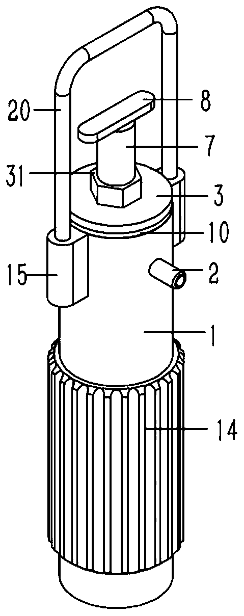
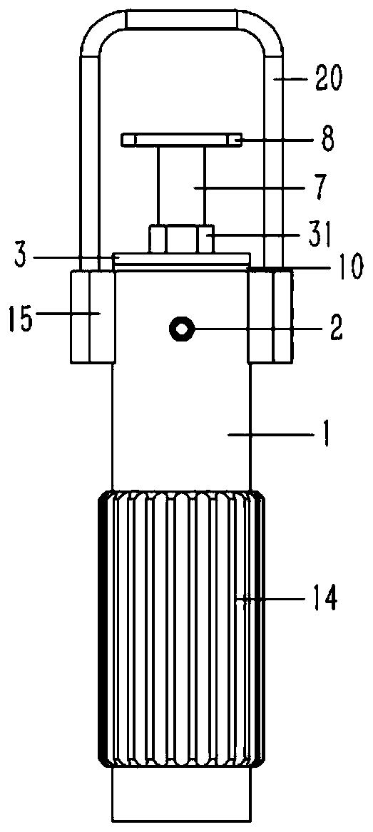
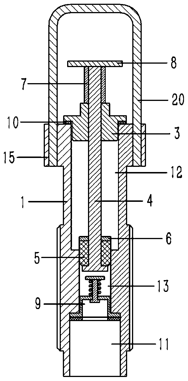
[0018] Example: see Figures 1 to 4 As shown, a self-contained faucet pressure test device includes a cylindrical container 1, the upper part of the container 1 is formed with a pressure chamber 12 passing through the upper end surface of the container 1, and the lower end surface of the container 1 is formed with a threaded connection hole 11, The bottom surface of the threaded connection hole 11 is formed with a guide hole 13 that communicates with the pressure chamber 12. The upper end of the container 1 is inserted and fixed with a valve 2 that communicates with the pressure chamber 12. The guide hole 13 of the container 1 is inserted with an inverted T-shaped The pull rod 4 is fixed with an annular rubber seal sleeve 5 on the upper sleeve of the T-shaped pull rod 4, and the rubber seal sleeve 5 is pressed against the inner wall of the guide hole 13; the upper end of the T-shaped pull rod 4 passes through the end cover 3. A sleeve 7, a horizontal handle 8 is fixed on the u...


PUM


Abstract

The invention discloses an independent faucet pressure resistance testing device. The device comprises a cylindrical container. A pressure cavity penetrating through the upper end surface of the container is formed above the container. A threaded connecting hole is formed in the lower end surface of the container. A guide hole communicated with the pressure cavity is formed in the bottom surface of the threaded connection hole, an inflating valve communicated with the pressure cavity is inserted and fixed to the upper end of the container, an inverted T-shaped pull rod is inserted into the guide hole of the container, an annular rubber sealing sleeve is inserted and fixed to the T-shaped pull rod in a sleeving mode, and the rubber sealing sleeve abuts against the inner wall of the guide hole in a pressing mode. A horizontal handle is fixed at the upper end of the T-shaped pull rod. The end cover is fixed at the upper end of the container. Lug bases are formed on the outer walls of thetwo opposite sides of the upper end of the container, a U-shaped handle is arranged above the handle, and the two ends of the handle are fixedly connected to the lug bases in an inserted mode. A checkring is fixed to the T-shaped pull rod in an inserted and sleeved mode and abuts against the upper end face of the rubber sealing sleeve.

Description

technical field [0001] The invention relates to the technical field of faucet testing equipment, in particular to an independent water faucet pressure testing device. Background technique [0002] At present, the production process of the faucet is mainly composed of four parts, one is casting, the other is machining, the third is surface treatment, and the fourth is assembly. After the assembly is completed, the faucet needs to be tested for air tightness to avoid leakage problems in the closed state of the faucet; At the same time, it is also necessary to carry out a pressure test on the faucet, because the faucet used in daily life has always been used under pressure; the existing faucet pressure measurement equipment connects a pressure tube to the faucet, and then uses the pressure tube to inject water into the faucet. The air is pressurized and kept under pressure, so as to observe whether there is leakage in the sink, the pressure test takes a long time, and the press...

Claims


Application Information

Patent Timeline
IPC IPC(8): G01N3/12G01N3/02
CPCG01N3/02G01N3/12G01N2203/0003G01N2203/0019G01N2203/0044
Inventor 林广华
Owner 林广华
Features
  • R&D
  • Intellectual Property
  • Life Sciences
  • Materials
  • Tech Scout
  • Unparalleled Data Quality
  • Higher Quality Content
  • 60% Fewer Hallucinations
Learn More