Method For Real-Time Monitoring and Transmitting Hydraulic Fracture Seismic Events to Surface Using the Pilot Hole of the Treatment Well as the Monitoring Well

a technology of hydraulic fracture and seismic event, applied in seismology for waterlogging, borehole/well accessories, surveillance, etc., can solve the problems of deformation of the hydraulic fracture, and difficulty in determining the size and orientation of the completed hydraulic fracture, so as to reduce the cost of fracture wrapping, reduce the effect of noise or elimination, and improve the effect of power and communication

Active Publication Date: 2013-04-11
SAUDI ARABIAN OIL CO
View PDF3 Cites 45 Cited by
  • Summary
  • Abstract
  • Description
  • Claims
  • Application Information

AI Technical Summary

Benefits of technology

[0036]Various embodiments of the present invention advantageously allow real time data transmission of seismic event data from the treatment well while pumping a hydraulic fracture treatment. Conventional practice is to drill an observation/monitoring well and to deploy geophones to monitor fracture seismic events during the fracture treatment or to deploy geophones at the surface. Often observation/monitoring wells or the surface is too far from the fracture treatment to allow collection of good quality monitoring data, and there substantial costs associated with establishing an observation/monitoring well. Accordingly, to solve such problems, various embodiments of the present invention advantageously provide for utilization of a single treatment well to perform fracture seismic mapping without a need for a separate monitoring well or surface equipment deployment. This can be accomplished by deploying the acoustic sensors downhole in a portion of the treatment well, below the sidetrack well used for delivering the fracturing fluid. This portion of the treatment well can be, for example, a portion of the pilot hole for the treatment well extending beyond the desired entrance location of the sidetrack well. Advantageously, use of, for example, the original pilot hole in a sidetrack provides a significant reduction in the cost of fracture wrapping by eliminating the drilling and completion of a separate monitoring well, which may typically cost $10.0 MM and 30-50 days of drilling rig time.
[0037]Various embodiments of the present invention also advantageously provide for isolating the acoustic sensors to provide for gathering acoustic data having an acceptable signal-to-noise ratio real-time during pumping, and/or provide for use of slurry concentrations greater than 4 PPA, by running the sensors below the kickover tool and/or installing a packer below the kickover tool to contain the acoustic sensors within the extended section of the main portion of the treatment well (e.g., the pilot hole)—separating the slurry carrying components and acoustic communications components so that they do not contact or otherwise communicate with each other. Advantageously, by placing the geophones below the kickover to

Problems solved by technology

Determining the size and orientation of completed hydraulic fractures is quite difficult and expensive, and in less expensive alternatives, highly inaccurate.
Further, availability of surface real estate or other factors can prevent the monitoring well from being drilled sufficiently close to the area of interest, and thus, results in a degraded performance.
Recognized by the inventors, however, is that as a result of the pumping of the fracturing fluid, such acoustic sensors located along the annulus of the treatment well or within the flow path encounter substantial noise during the hydraulic fracturing events, which in turn, results in the collection of acoustic data having

Method used


Image

  • Method For Real-Time Monitoring and Transmitting Hydraulic Fracture Seismic Events to Surface Using the Pilot Hole of the Treatment Well as the Monitoring Well
  • Method For Real-Time Monitoring and Transmitting Hydraulic Fracture Seismic Events to Surface Using the Pilot Hole of the Treatment Well as the Monitoring Well
  • Method For Real-Time Monitoring and Transmitting Hydraulic Fracture Seismic Events to Surface Using the Pilot Hole of the Treatment Well as the Monitoring Well

Examples


Embodiment Construction

[0050]The present invention will now be described more fully hereinafter with reference to the accompanying drawings, which illustrate embodiments of the invention. This invention may, however, be embodied in many different forms and should not be construed as limited to the illustrated embodiments set forth herein. Rather, these embodiments are provided so that this disclosure will be thorough and complete, and will fully convey the scope of the invention to those skilled in the art. Like numbers refer to like elements throughout. Prime notation, if used, indicates similar elements in alternative embodiments.

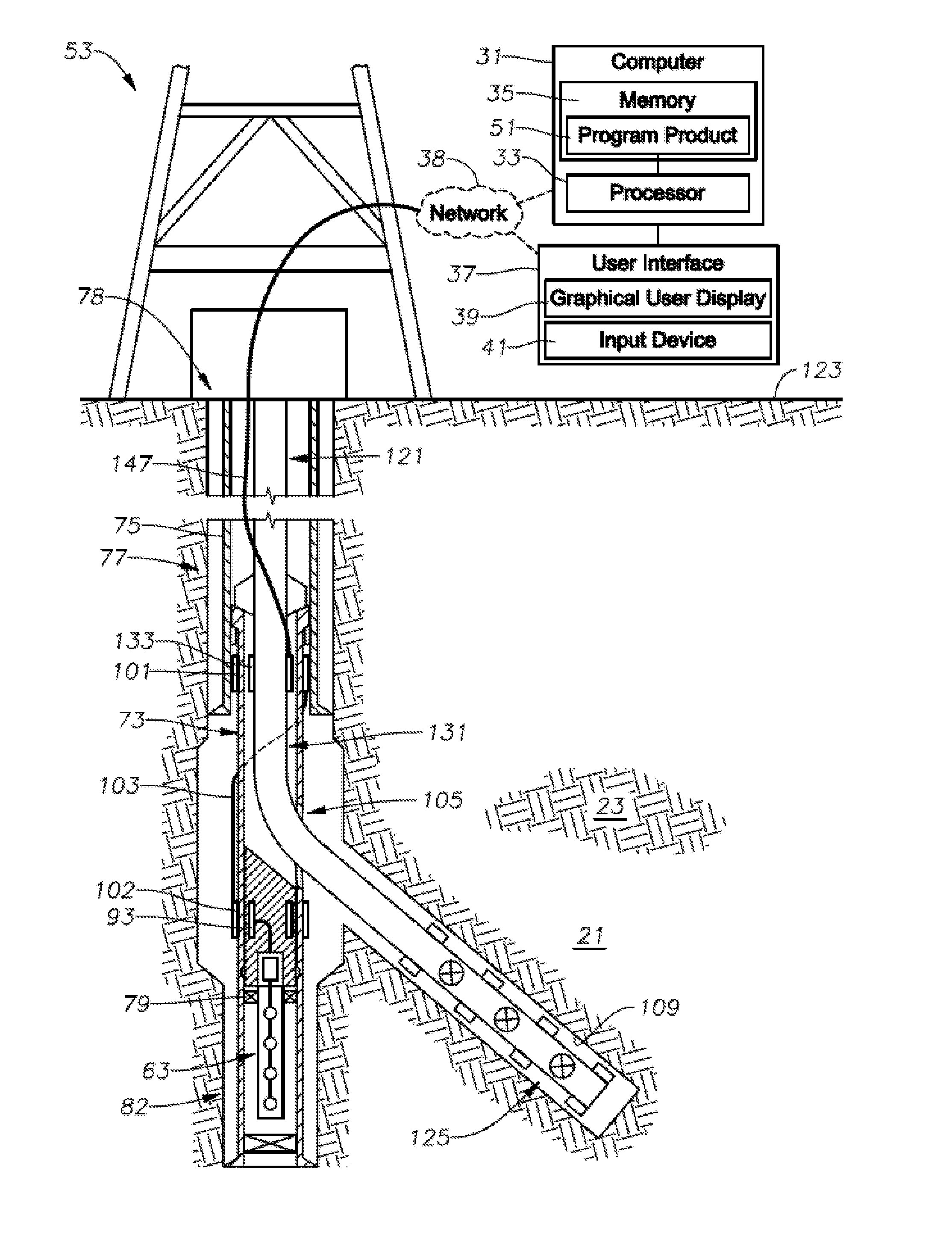
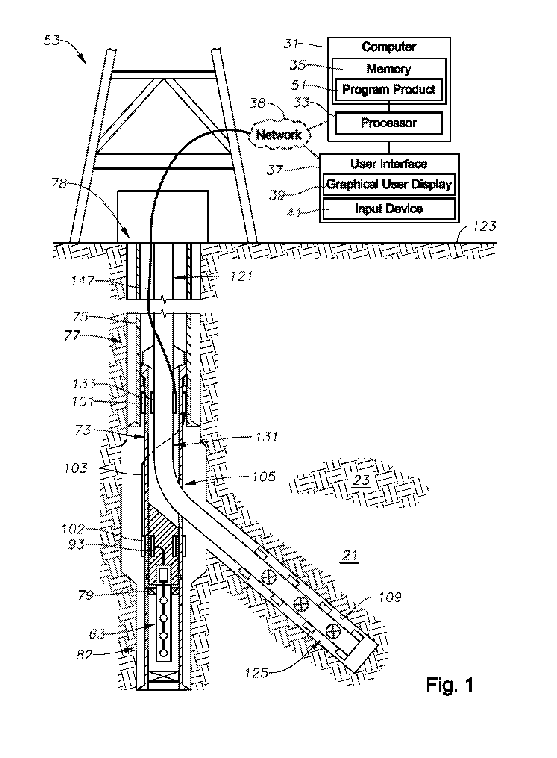
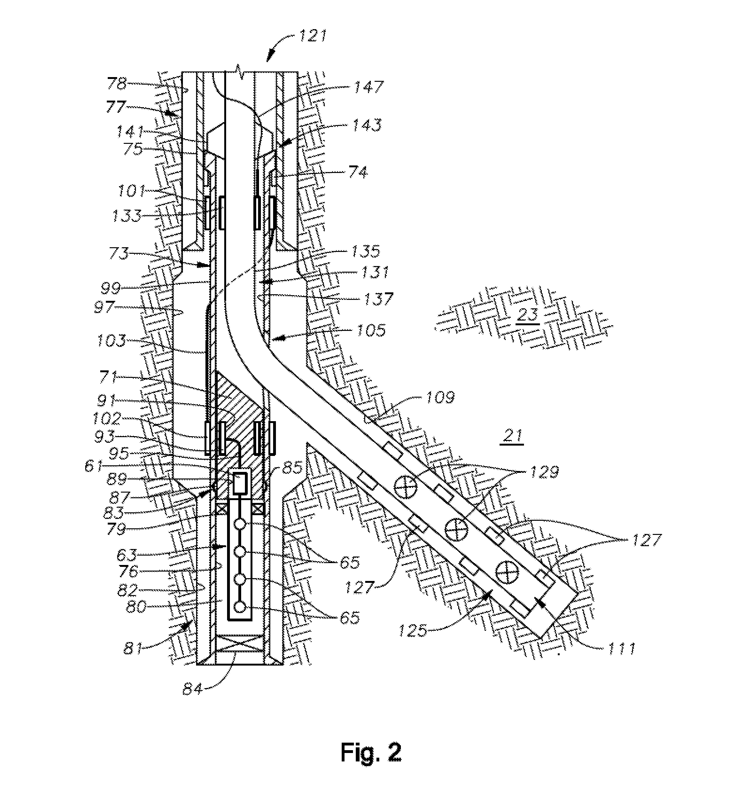
[0051]Various embodiments of the present invention advantageously provide systems and methods for real-time monitoring of hydraulic fractures using the treatment well pilot hole. According to an exemplary embodiment of the present invention, the well is drilled through the desired formation where the fracture treatment will take place. A kickover or other deflecting tool is the...


PUM


Abstract

Methods for determining hydraulic fracture geometry and/or areal extent of an area of interest in a reservoir, are provided. An exemplary method includes isolating downhole acoustic receiver equipment in a lower portion of a first wellbore from fracturing operations located in a second wellbore connected to the first wellbore. Communications between surface equipment in the downhole acoustic receiver equipment is provided through a communications conduit bypass that permits well operations in the second wellbore without interfering with communications between the surface equipment and the downhole acoustic receiver equipment.

Description

RELATED APPLICATIONS [0001]This application is related to U.S. Non-Provisional Patent Application No. ______, titled “System For Real-Time Monitoring and Transmitting Hydraulic Fracture Seismic Events To Surface Using The Pilot Hole Of The Treatment Well As the Monitoring Well,” filed on Oct. 9, 2011, incorporated herein by reference in it's entirety.BACKGROUND OF THE INVENTION[0002]1. Field of the Invention[0003]The present invention relates in general to the field of hydraulic fracturing, monitoring, and data transmission of microseismic information from a zone of interest within a reservoir, and more particularly, to the utilization and employment of electrically and physically isolated downhole acoustic monitoring equipment within a fracturing treatment well to detect microseismic events during fracturing operations.[0004]2. Description of the Related Art[0005]Hydraulic fracturing has been used for over 60 years in more than one million wells to improve the productivity of a hyd...

Claims


Application Information

Patent Timeline
IPC IPC(8): E21B47/00
CPCE21B41/0035E21B43/30E21B17/028G01V1/40E21B43/26E21B47/101E21B47/122E21B47/107E21B47/13E21B17/0283
Inventor BARTKO, KIRK M.BOULDIN, BRETT WAYNE
Owner SAUDI ARABIAN OIL CO
Why Eureka
Try Eureka