Scattering point delay parameter calibration method and system

A technology of delay parameters and calibration methods, applied in radio wave measurement systems, instruments, etc., can solve the problem of inability to read the delay parameters of scattering points with an oscilloscope, and achieve the effect of extensive measurement and calibration

Inactive Publication Date: 2020-08-18
BEIJING INST OF RADIO METROLOGY & MEASUREMENT
View PDF18 Cites 0 Cited by
  • Summary
  • Abstract
  • Description
  • Claims
  • Application Information

AI Technical Summary

Problems solved by technology

[0006] This application proposes a multi-scattering point delay parameter calibration method and system, which solves the problem that when the delay difference of multiple scattering points is smaller than the pulse width, the echo signals of multiple scattering points will be superimposed together, and it is impossible to read each Delay parameters of scattering points, so it is impossible to measure and calibrate the delay parameters of multi-scattering points of broadband radar echo simulator

Method used


Image

  • Scattering point delay parameter calibration method and system
  • Scattering point delay parameter calibration method and system
  • Scattering point delay parameter calibration method and system

Examples


Embodiment Construction

[0024] In order to make the purpose, technical solution and advantages of the present application clearer, the technical solution of the present application will be clearly and completely described below in conjunction with specific embodiments of the present application and corresponding drawings. Apparently, the described embodiments are only some of the embodiments of the present application, rather than all the embodiments. Based on the embodiments in this application, all other embodiments obtained by persons of ordinary skill in the art without making creative efforts belong to the scope of protection of this application.

[0025] The technical solutions provided by various embodiments of the present application will be described in detail below in conjunction with the accompanying drawings.

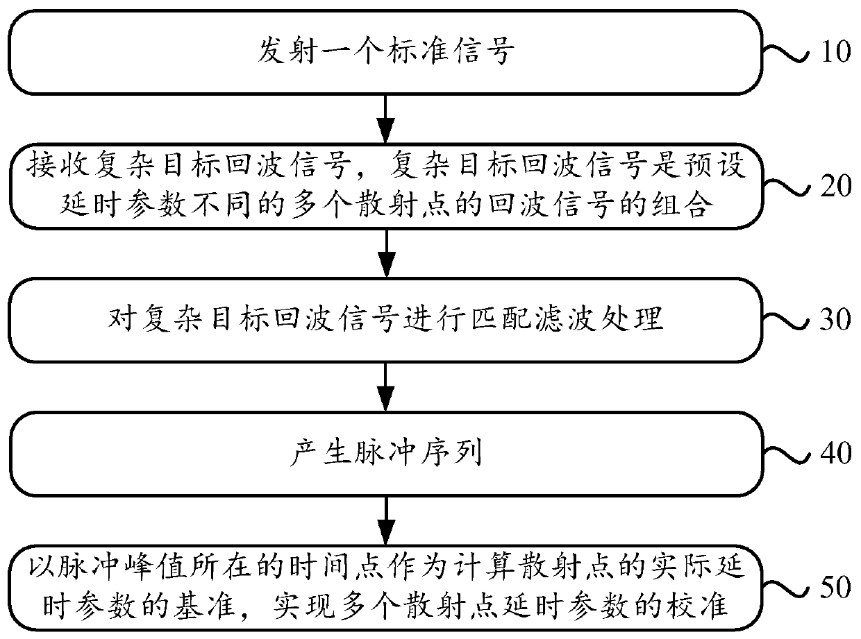
[0026] figure 1 It is a flow chart of an embodiment of the method for calibrating the time delay parameters of scattered points in this application. The method is shown below.

...


PUM


Abstract

The invention discloses a multi-scattering-point delay parameter calibration method and system. The method comprises the following steps: transmitting a standard signal, receiving a complex target echo signal, carrying out matched filtering on the complex target echo signal to generate a pulse sequence, and taking a time point where a pulse peak value is located as a reference for calculating an actual delay parameter of a scattering point. The system is used for calibrating an echo simulator, and the echo simulator is used for generating a complex target echo signal. A signal generation unitis used for transmitting a standard signal; a signal acquisition unit is used for respectively performing high-speed ADC acquisition on the complex target echo signal and the standard signal; and a signal processing unit is used for carrying out matched filtering on the complex target echo signal to generate a pulse sequence, and taking a time point where a pulse peak value is located as a reference for calculating an actual delay parameter of the scattering point. According to the invention, measurement and calibration of multi-scattering-point delay parameters are realized.

Description

technical field [0001] The present application relates to the technical field of microwave measurement, in particular to a method and system for calibrating time delay parameters of scattering points. Background technique [0002] As an important guarantee resource for radar performance testing, the radar echo simulator is widely used in the field of radar research and development. The accuracy of the simulated echo of the radar echo simulator plays a vital role in the results of the radar performance test. It is of great significance to calibrate the scattering point characteristics of the echo generated by the echo simulator. The traditional radar system transmits narrow-band radar signals and obtains the echo information formed by a single ideal point. The early radar echo simulator simulates the echo of a single scattering point. For the case of a single scatter point, the parameters of the scatter point can be calibrated for the radar echo simulator through standard in...

Claims


Application Information

Patent Timeline
Patent Type & Authority Applications(China)
IPC IPC(8): G01S7/40
CPCG01S7/4052
Inventor 贾琳曹宇楚学胜吴双
Owner BEIJING INST OF RADIO METROLOGY & MEASUREMENT
Why Eureka
Try Eureka