A digital measurement method and device for modulation delay of an optical frequency modulator

A measurement method and modulator technology, applied in the direction of measuring devices, measuring ultrasonic/sonic/infrasonic waves, instruments, etc., can solve the unsolved problems of optical frequency modulators, achieve small filtering effect, high time resolution, and high measurement accuracy degree of effect

Active Publication Date: 2021-11-30
BEIJING CHANGCHENG INST OF METROLOGY & MEASUREMENT AVIATION IND CORP OF CHINA
View PDF4 Cites 0 Cited by
  • Summary
  • Abstract
  • Description
  • Claims
  • Application Information

AI Technical Summary

Problems solved by technology

However, the measurement problem of the delay characteristics of the optical frequency modulator itself has not been solved. The biggest difficulty is that the control signal of the optical frequency modulator itself is a frequency modulation signal in which the radio frequency sine wave is the carrier and the audio sine wave is the modulation waveform. The vibration mode and the light wave diffraction effect produce a frequency modulation effect on the passing optical frequency signal, and finally produce a frequency modulation result on the passing laser signal. It belongs to an optical, mechanical and electrical system integrating mechanical, electronic and optical effects. The part that needs to be accurately measured is the delay time of the modulated optical frequency signal to the excited electrical modulation signal

Method used


Image

  • A digital measurement method and device for modulation delay of an optical frequency modulator
  • A digital measurement method and device for modulation delay of an optical frequency modulator
  • A digital measurement method and device for modulation delay of an optical frequency modulator

Examples


Embodiment

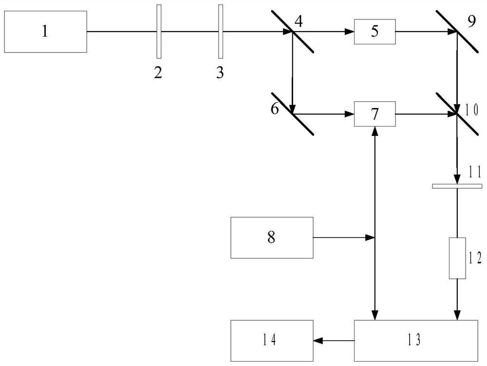
[0090] A measuring method and device for an optical frequency modulator, the structure of which is as follows figure 1 As shown, it includes a frequency-stabilized laser 1, a polarizer 2, a λ / 2 wave plate 3, a beam splitter 4, a frequency shifter 5, a mirror 6, a measured optical frequency modulator 7, a modulation signal source 8, a mirror 9, Half mirror 10, polarizer 11, photodetector 12, digital oscilloscope 13, electronic computer 14.

[0091] Specific to this embodiment:

[0092] First, the frequency-stabilized laser light emitted by the frequency-stabilized laser 1 is divided into two by the polarizer 2, the λ / 2 wave plate 3, and the beam splitter 4, and one path is frequency-shifted by the frequency shifter 5 d After that, it passes through the reflector 9, passes through the half-mirror 10, and interferes with another beam combination, passes through the polarizer 11 and enters the photodetector 12 for reception; the other pass passes through the reflector 6, injects ...


PUM


Abstract

The invention relates to a digital measurement method and device for modulation delay of an optical frequency modulator, and belongs to the technical field of photoelectric measurement. The device includes a frequency-stabilized laser, a polarizer, a λ / 2 wave plate, a beam splitter, a frequency shifter, a reflector, a measured optical frequency modulator, a modulated signal source, a reflector, a half mirror, a polarizer 11, Photodetectors, digital oscilloscopes, electronic computers. The measured object is the delay time between the excitation control signal of the optical frequency modulator and the regulated optical frequency signal; the laser frequency regulation signal waveform of the optical frequency modulator is obtained by using a heterodyne laser interferometry device, and the optical frequency is measured. The signal is converted into an electrical signal. The method can achieve good convergence, high measurement accuracy, and good adaptability to the situation that the carrier is non-stationary and the amplitude envelope changes sharply.

Description

technical field [0001] The invention relates to a digital measurement method and device for modulation delay of an optical frequency modulator, belonging to the technical field of photoelectric measurement. Background technique [0002] The laser vibrometer is a general-purpose, basic vibration and shock measuring instrument with high precision, non-contact, and no additional interference and influence on the measured object. The measurement and calibration of it has always been a difficult problem in the industry, mainly because Its excitation is the movement value (displacement, velocity, acceleration), and the measurement principle used is carried out through the laser Doppler effect. It needs to perceive the physical movement through the change of optical frequency, and the output is given in the form of electrical signal data. Various aspects such as mechanical movement, optical frequency control, and electronic measurement. Usually, its measurement and calibration are...

Claims


Application Information

Patent Timeline
Patent Type & Authority Patents(China)
IPC IPC(8): G01H9/00
CPCG01H9/00
Inventor 梁志国朱振宇张合富
Owner BEIJING CHANGCHENG INST OF METROLOGY & MEASUREMENT AVIATION IND CORP OF CHINA
Why Eureka
Try Eureka