
Method, device and system for determining position of moving mechanism and engineering machine

A mobile mechanism and construction machinery technology, applied in two-dimensional position/channel control, transmission system, control/regulation system, etc., can solve the problem of inability to accurately obtain the position of the material distribution trolley, waste of energy consumption, and inability to judge whether the left side or the right side, etc. question

Active Publication Date: 2020-08-18
湖南中联重科混凝土机械站类设备有限公司 +1
View PDF7 Cites 0 Cited by
  • Summary
  • Abstract
  • Description
  • Claims
  • Application Information

AI Technical Summary

Problems solved by technology

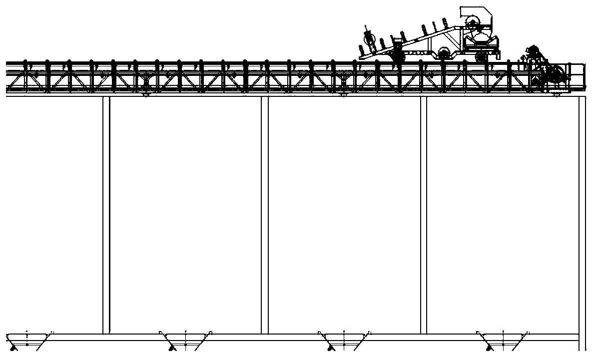
[0006] The current method of discrete position signals cannot accurately obtain the position of the material distribution trolley. When the material distribution trolley is in the non-inductive switch position, the system will not receive any signal from any sensor switch, so the human-computer interaction cannot display the material distribution. The actual position of the trolley. At this time, if the human-computer interaction orders the distributing trolley to move to a certain position, the system will not be able to judge whether the target position is to the left or right of the current position, resulting in uncertainty of the trolley running direction, which can only be determined randomly. One movement direction, until the feeding trolley reaches a certain position of the sensor switch, it is re-judged whether the direction is correct, this method will cause low efficiency and waste of energy consumption; or manually judge the actual position of the feeding trolley before the human-computer interaction orders , and according to the actual situation, artificially control the movement of the trolley to the nearest sensor switch position, and then issue instructions, but this method is contrary to automatic control

Method used


Image

  • Method, device and system for determining position of moving mechanism and engineering machine
  • Method, device and system for determining position of moving mechanism and engineering machine
  • Method, device and system for determining position of moving mechanism and engineering machine

Examples


Embodiment Construction

[0030] Specific embodiments of the present invention will be described in detail below in conjunction with the accompanying drawings. It should be understood that the specific embodiments described here are only used to illustrate and explain the present invention, and are not intended to limit the present invention.

[0031] An aspect of an embodiment of the invention provides a method for determining a position of a movement mechanism. Wherein, in the embodiment of the present invention, the position signal transmitting module is installed at a fixed position on the moving track of the moving mechanism, and the position signal transmitting module is triggered to send a position signal when the moving mechanism reaches the position where the position signal transmitting module is located. The number of installed position signal transmitting modules may be determined according to actual conditions. In addition, in the embodiment of the present invention, when the position sig...


PUM


Abstract

The invention relates to the technical field of engineering machinery. The invention discloses a method, device and system for determining the position of a moving mechanism and engineering machinery,and the method comprises the steps: determining a digitalized position corresponding to a position signal based on a preset digitalized position rule under the condition that the position signal is received, and updating the current position of the moving mechanism to the digitalized position; in the case that the position signal is not received, determining a position signal transmitting moduletriggered before the moving mechanism moves to the current position and a moving direction of the moving mechanism moving to the current position; and determining a digital position corresponding to the current position of the moving mechanism based on the determined position signal emitted by the position signal emission module, the moving direction and a preset digital position rule, and updating the current position of the moving mechanism to the determined digital position. Therefore, the position of the moving mechanism can be determined relatively accurately.

Description

technical field [0001] The present invention relates to the technical field of construction machinery, in particular to a method, device and system for determining the position of a moving mechanism and construction machinery. Background technique [0002] Affected by factors such as the particularity of concrete sand and gravel raw materials, land use restrictions, and environmental protection, concrete production companies are increasingly inclined to use silos to hoard sand and gravel raw materials, such as figure 1 As shown, the same floor area can store more materials. [0003] According to the structural characteristics of the material warehouse, when the materials are put into the warehouse, the materials are generally lifted in the form of inclined belts, etc., and then used in the form of snake-shaped material distribution belts, walking material distribution belts, etc. for fixed-point transportation. To simplify the description, the following walks The distributi...

Claims


Application Information

Patent Timeline
IPC IPC(8): G05D1/02H04B1/40
CPCG05D1/0225H04B1/40
Inventor 蒋敦杨卫东廖超曾智狄玄佳
Owner 湖南中联重科混凝土机械站类设备有限公司
Features
  • Generate Ideas
  • Intellectual Property
  • Life Sciences
  • Materials
  • Tech Scout
  • Unparalleled Data Quality
  • Higher Quality Content
  • 60% Fewer Hallucinations
Learn More