
Flue gas purification system

A flue gas purification system and gas outlet technology, which are applied in the field of flue gas purification, can solve the problem of easy backflow of flue gas, and achieve the effects of solving easy backflow of flue gas and prolonging service life.

Pending Publication Date: 2020-08-21
常州市永热太阳能设备有限公司
View PDF0 Cites 0 Cited by
  • Summary
  • Abstract
  • Description
  • Claims
  • Application Information

AI Technical Summary

Problems solved by technology

[0004] In order to solve the technical problem that the flue gas in the incinerator is easy to flow back in the prior art, the present invention provides a flue gas purification system, which solves the above-mentioned technical problem

Method used


Image

  • Flue gas purification system
  • Flue gas purification system
  • Flue gas purification system

Examples


Embodiment Construction

[0034] The following will clearly and completely describe the technical solutions in the embodiments of the present invention in conjunction with the accompanying drawings in the embodiments of the present invention. Obviously, the described embodiments are only some of the embodiments of the present invention, not all of them. The following description of at least one exemplary embodiment is merely illustrative in nature and is in no way intended as any limitation of the invention, its application or uses. Based on the embodiments of the present invention, all other embodiments obtained by persons of ordinary skill in the art without making creative efforts all belong to the protection scope of the present invention.

[0035] It should be noted that the terminology used here is only for describing specific implementations, and is not intended to limit the exemplary implementations according to the present application. As used herein, unless the context clearly indicates other...


PUM


Abstract

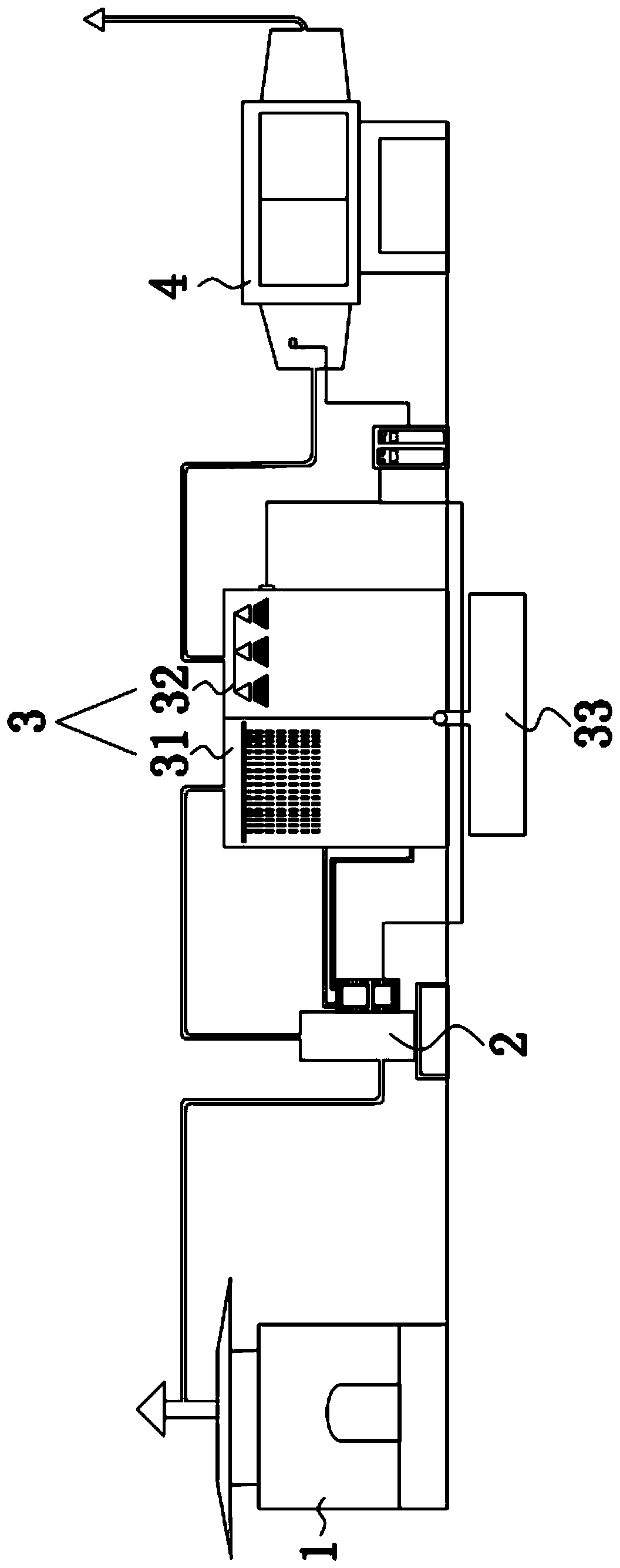
The invention relates to the field of flue gas purification, in particular to a flue gas purification system. The flue gas purification system comprises an incinerator, a fan, a separation box and anelectrostatic dust collector, wherein a flue gas outlet of the incinerator is connected with an air suction port of the fan; an exhaust port of the fan is connected with an air inlet of the separationbox; an air outlet of the separation box is connected with an inlet of the electrostatic dust collector; and an outlet of the electrostatic dust collector is connected to the outside so as to discharge purified gas. The flue gas purification system solves the technical problem that flue gas in an incinerator easily flows back in the prior art.

Description

technical field [0001] The invention relates to the field of flue gas purification, in particular to a flue gas purification system. Background technique [0002] As the gas purification equipment in the environmental protection equipment, the flue gas purification device is mainly used to evolve and purify the polluted gas to meet the national emission standards. The flue gas purification device for the incinerator is mainly to purify the flue gas at the outlet of the incinerator. The flue gas purification device mainly includes an induced draft system and a cleaning system. [0003] However, the fans in the air induction system of the existing flue gas purification devices are all arranged at the end of the electrostatic precipitator of the whole flue gas purification system. Too fast, so the negative pressure generated by the fan is relatively small, and the pressure drop along the entire flue gas purification system is relatively large, which makes the negative pressure...

Claims


Application Information

Patent Timeline
Patent Type & Authority Applications(China)
IPC IPC(8): B01D50/00
CPCB01D50/00
Inventor 秦超秦兴福
Owner 常州市永热太阳能设备有限公司
Learn More