Automatic TAPE attaching machine
An attaching machine, a pair of technology, applied in the field of machinery, can solve the problems of low efficiency, scratches, sticking deviation, etc., to achieve the effect of improving the overall efficiency, reducing the defective rate and increasing the precision
- Summary
- Abstract
- Description
- Claims
- Application Information
AI Technical Summary
Problems solved by technology
Method used
Image

Examples
Embodiment 1
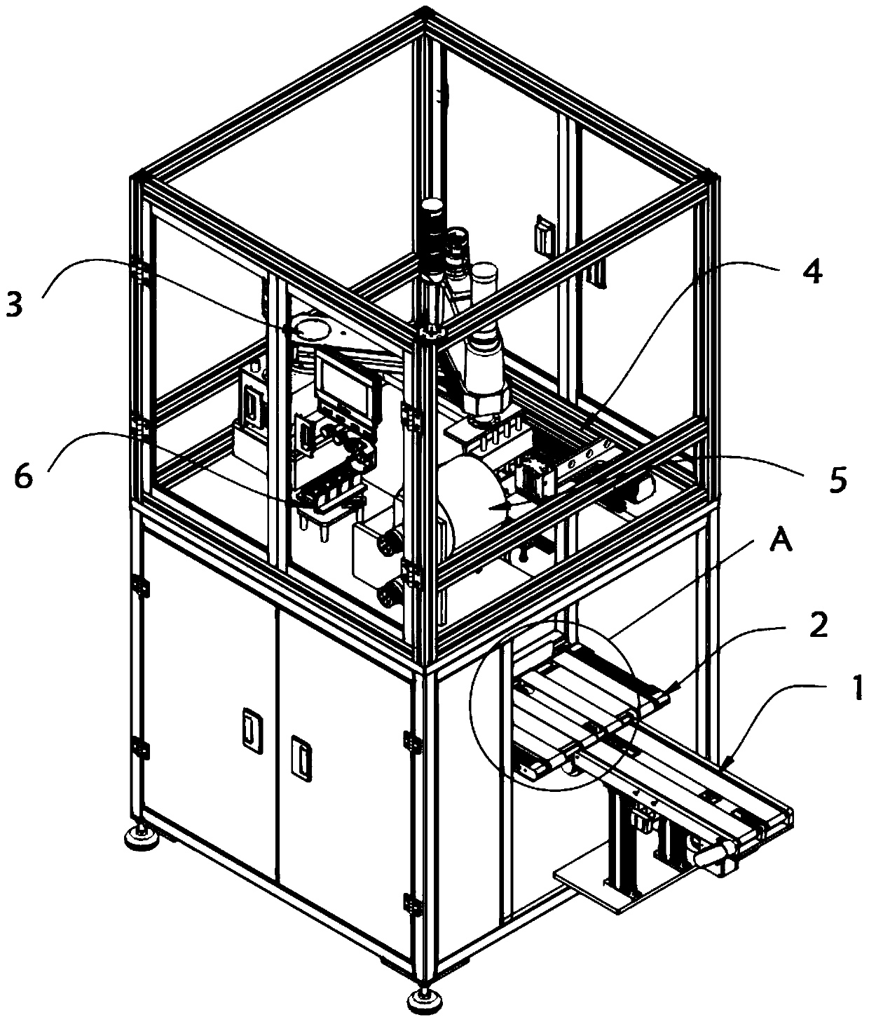
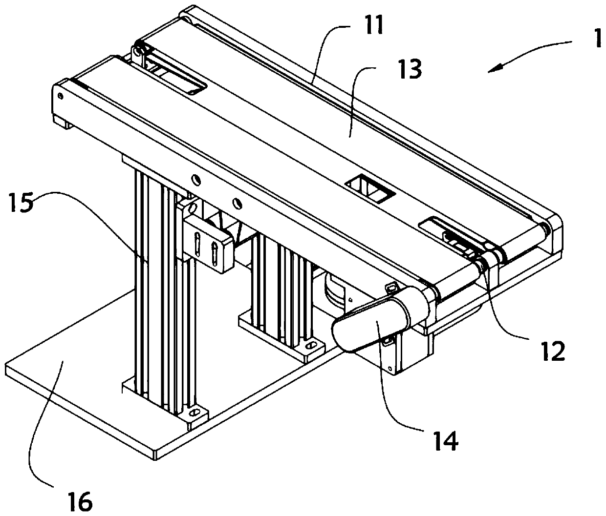
[0031] A kind of automatic TAPE attaching machine, such as figure 1 with figure 2 As shown, the lower cabinet body 7 and the upper frame body 8 are included, and the lower cabinet body 7 is equipped with a feeding conveying device 1 and a feeding conveying device 2 respectively, and the feeding conveying device 2 is installed on the feeding conveying device 1 side, and the upper frame body The outer surface of 8 is respectively equipped with grabbing film sticking mechanism 3, tray grabbing mechanism 4, film feeding device 5 and film sticking alignment fixture 6, feeding and conveying device 1 includes a pair of first mounting plates 11, two first mounting plates 11 First connecting shafts 12 are installed at the two ends respectively, and a feeding conveyor belt 13 is arranged between the two first connecting shafts 12. One end of one of the first connecting shafts 12 is provided with a first rotating motor 14, and the first mounting plate 11 A supporting leg 15 is installe...
Embodiment 2
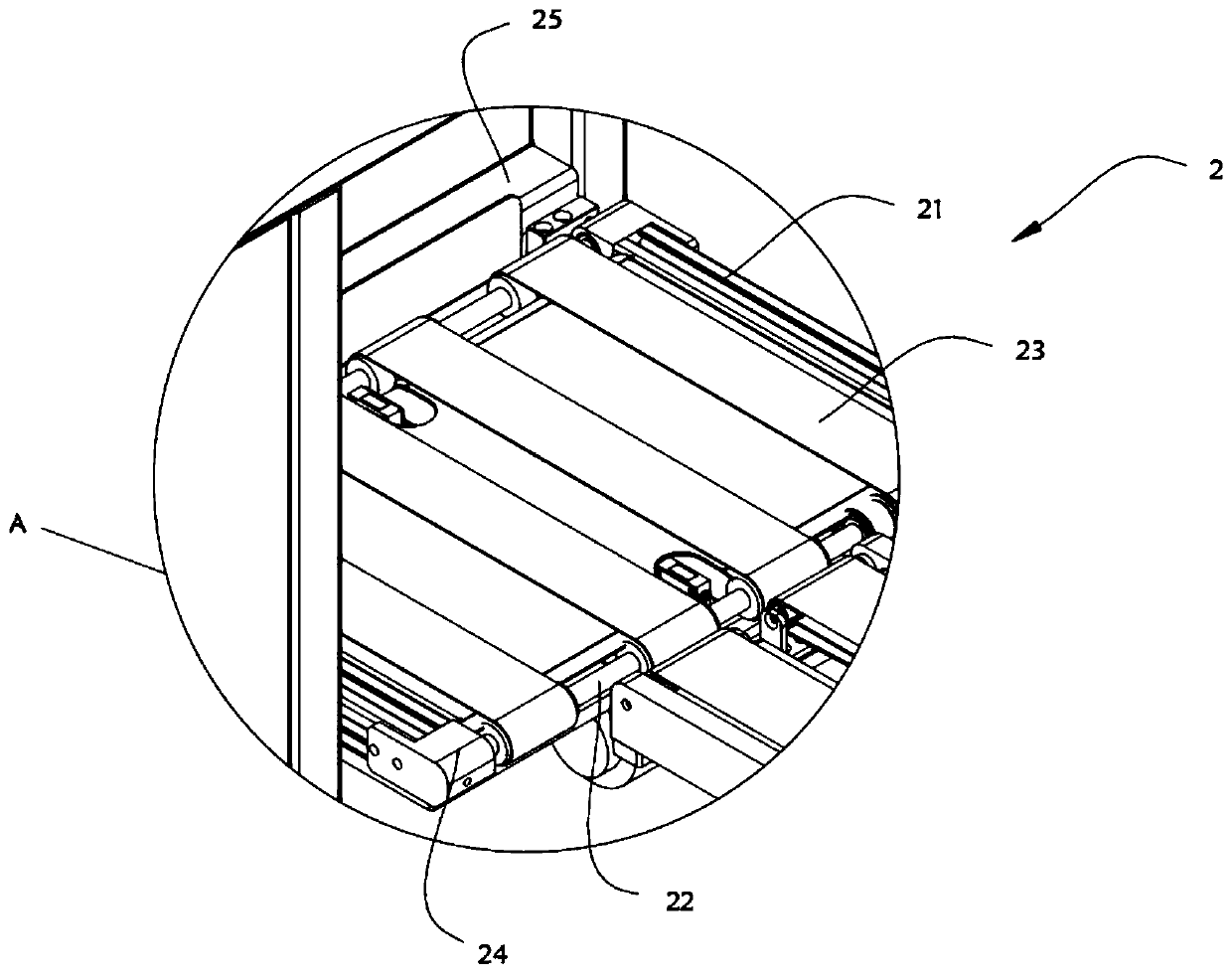
[0035] As the second embodiment of the present invention, in order to facilitate the loading of the patches, the inventors are provided with a feeding conveying device 2, as a preferred embodiment, such as image 3 with Figure 4 As shown, the feeding conveying device 2 includes a pair of second mounting plates 21, the two ends of the second mounting plates 21 are respectively equipped with a second connecting shaft 22, and a feeding shaft 22 is arranged between the two second connecting shafts 22. Conveyor belt 23, one end of one of the second connecting shafts 22 is provided with a second rotating motor 24, one end of the second mounting plate 21 is provided with a slide plate 25, the bottom of the slide plate 25 is equipped with a hydraulic cylinder 26, and the lower cabinet 7 is close to the feeding conveying device 2. One side is provided with feeding slide rail 27, and slide plate 25 and feeding slide rail 27 slide fit.
[0036] In this embodiment, the second rotating e...
Embodiment 3
[0040] As a third embodiment of the present invention, in order to facilitate the grabbing and shipping of the film, the inventors are provided with a grabbing film mechanism 3, as a preferred embodiment, such as Figure 5 As shown, the gripping film sticking mechanism 3 includes a motor base 31, a first servo motor 32 is installed on the top of the motor base 31, a first connecting arm 33 is installed on the output shaft of the first servo motor 32, and the other of the first connecting arm 33 One end is provided with the second connecting arm 34, the second connecting arm 34 is equipped with the second servomotor 35 near the first connecting arm 33 end, the other end of the second connecting arm 34 is equipped with the 3rd servomotor 36, the 3rd servomotor 36 A vacuum suction cup 37 is installed at the bottom of the bottom, and the first connecting arm 33 and the second connecting arm 34 are rotatably fitted.
[0041] In this embodiment, the first servo motor 32, the second ...
PUM
 Abstract
Description
Claims
Application Information
 - Generate Ideas
- Intellectual Property
- Life Sciences
- Materials
- Tech Scout
- Unparalleled Data Quality
- Higher Quality Content
- 60% Fewer Hallucinations
Browse by: Latest US Patents, China's latest patents, Technical Efficacy Thesaurus, Application Domain, Technology Topic, Popular Technical Reports.
© 2025 PatSnap. All rights reserved.Legal|Privacy policy|Modern Slavery Act Transparency Statement|Sitemap|About US| Contact US: help@patsnap.com